Diagnostic Manual, Body and Accessories,
Volume 3
Electrical Test Program - Survey of Electrical Valve Actuation
|
| Operational sequence, soft top opening |
Valves being controlled at time of
operational sequence
When testing with HHT
Up corresponds to 11 - 14 V
Closed corresponds to 0 - 1 V |
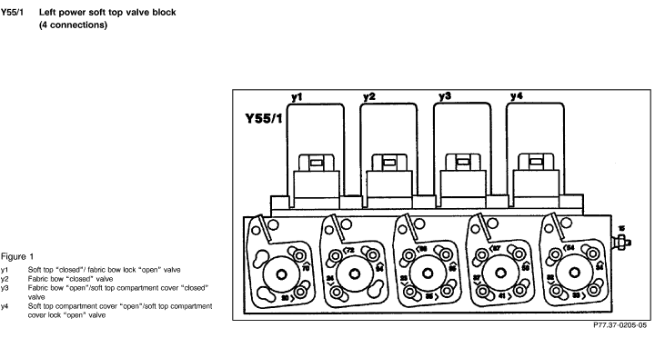
Left power soft top valve block (Y55/1) |
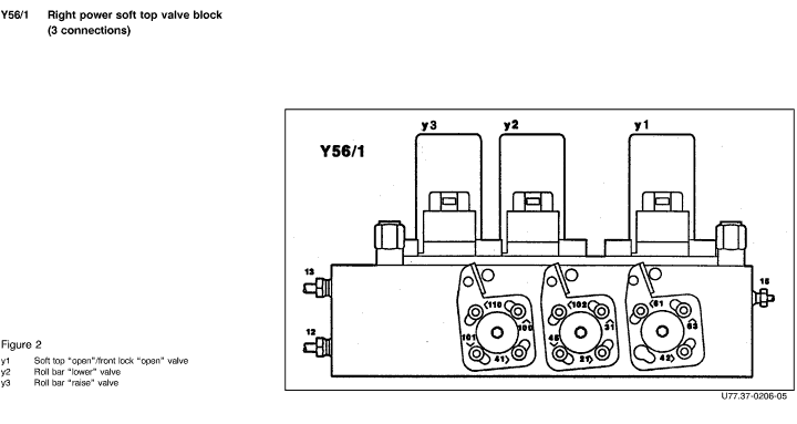
Right power soft top valve block (Y56/1) |
| Fabric bow "closed" valve (y2) |
Fabric bow "open"/soft top compartment cover
"closed" valve (y3) |
Soft top "open"/front lock "open" valve (y1) |
Roll bar "raise" valve (y3) |
Roll bar "lower" valve, Hydraulic actuator (y2) |
Connection Diagram - Socket Box to
Connector (X2) ( 22, Figure 2) 22, Figure 2) |
X2 
 37 37 |
X2 
 36 36 |
X2 
 55 55 |
X2 
 18 18 |
X2 
 19 19 |
X2 
 17 17 |
X2 
 54 54 |
Lower roll bar,
lower side windows |
0-1 V |
0-1 V |
0-1 V |
0-1 V |
0-1 V |
0-1 V |
11-14 V |
| Unlock fabric bow |
0-1 V |
11-14 V |
0-1 V |
0-1 V |
0-1 V |
0-1 V |
11-14 V |
| Raise fabric bow |
0-1 V |
11-14 V |
0-1 V |
11-14 V |
0-1 V |
0-1 V |
11-14 V |
| Unlock, open soft top compartment
cover |
11-14 V |
0-1 V |
0-1 V |
11-14 V |
0-1 V |
0-1 V |
11-14 V |
| Unlock front soft top |
11-14 V |
11-14 V |
0-1 V |
11-14 V |
11-14 V |
0-1 V |
11-14 V |
| Open soft top |
11-14 V |
0-1 V |
0-1 V |
11-14 V |
11-14 V |
0-1 V |
11-14 V |
| Lower soft top in soft top compartment |
11-14 V |
0-1 V |
0-1 V |
11-14 V |
11-14 V |
0-1 V |
11-14 V |
| Close, lock soft top compartment
cover |
0-1 V |
0-1 V |
0-1 V |
11-14 V |
11-14 V |
0-1 V |
11-14 V |
| Raise roll bar, raise side windows |
0-1 V |
0-1 V |
0-1 V |
0-1 V |
0-1 V |
11-14 V |
11-14 V |
| Operational sequence, soft top closing |
Valves being controlled at time of
operational sequence
When testing with HHT
Up corresponds to 11 - 14 V
Closed corresponds to 0 - 1 V |
Left power soft top valve block (Y55/1) |
Right power soft top valve block (Y56/1) |
| Fabric bow "closed" valve (y2) |
Fabric bow "open"/soft top compartment cover
"closed" valve (y3) |
Soft top "open"/front lock "open" valve (y1) |
Roll bar "raise" valve (y3) |
Roll bar "lower" valve, Hydraulic actuator (y2) |
Connection Diagram - Socket Box to
Connector (X2) ( 22, Figure 2) 22, Figure 2) |
X2 
 37 37 |
X2 
 36 36 |
X2 
 55 55 |
X2 
 18 18 |
X2 
 19 19 |
X2 
 17 17 |
X2 
 54 54 |
| Lower roll bar, lower side windows |
0-1 V |
0-1 V |
0-1 V |
0-1 V |
0-1 V |
0-1 V |
11-14 V |
| Unlock, open soft top compartment
cover |
11-14 V |
0-1 V |
0-1 V |
11-14 V |
0-1 V |
0-1 V |
11-14 V |
| Close soft top |
11-14 V |
11-14 V |
0-1 V |
11-14 V |
0-1 V |
0-1 V |
11-14 V |
| Close soft top (Differential operation,
after approximately 6 seconds) |
11-14 V |
11-14 V |
0-1 V |
11-14 V |
11-14 V |
0-1 V |
11-14 V |
| Lock front soft top (Activate for
0.5 seconds) |
11-14 V |
0-1 V |
0-1 V |
11-14 V |
0-1 V |
0-1 V |
0-1 V |
| Lock front soft top |
11-14 V |
11-14 V |
0-1 V |
11-14 V |
0-1 V |
0-1 V |
11-14 V |
| Close, lock soft top compartment
cover |
0-1 V |
11-14 V |
0-1 V |
11-14 V |
0-1 V |
0-1 V |
11-14 V |
| Lower fabric bow |
0-1 V |
11-14 V |
11-14 V |
0-1 V |
0-1 V |
0-1 V |
11-14 V |
| Lock fabric bow |
0-1 V |
0-1 V |
11-14 V |
0-1 V |
0-1 V |
0-1 V |
11-14 V |
| Raise roll bar, raise side windows |
0-1 V |
0-1 V |
0-1 V |
0-1 V |
0-1 V |
11-14 V |
11-14 V |
| Operational sequence, hardtop locking |
Valves being controlled at time of operational
sequence
When testing with HHT
Up corresponds to 11 - 14 V
Closed corresponds to 0 - 1 V |
Left power soft top valve block (Y55/1) |
Right power soft top valve block (Y56/1) |
| Fabric bow "open"/soft top compartment cover "closed" valve
(y3) |
Fabric bow "closed" valve (y2) |
Soft top "open"/front lock "open" valve (y1) |
Roll bar "raise" valve (y3) |
Roll bar "lower" valve, Hydraulic actuator (y2) |
Connection Diagram - Socket Box to
Connector (X2) ( 22, Figure 2) 22, Figure 2) |
X2 
 37 37 |
X2 
 36 36 |
X2 
 18 18 |
X2 
 55 55 |
X2 
 19 19 |
X2 
 17 17 |
X2 
 54 54 |
| Hardtop attached (for approximately
3 seconds) |
0-1 V |
11-14 V |
0-1 V |
0-1 V |
11-14 V |
0-1 V |
11-14 V |
| front |
0-1 V |
0-1 V |
0-1 V |
0-1 V |
11-14 V |
0-1 V |
11-14 V |
| rear |
0-1 V |
0-1 V |
0-1 V |
0-1 V |
0-1 V |
0-1 V |
11-14 V |
| Operational sequence, hardtop unlocking |
Valves being controlled at time of operational
sequence
When testing with HHT
Up corresponds to 11 - 14 V
Closed corresponds to 0 - 1 V |
Left power soft top valve block (Y55/1) |
Right power soft top valve block (Y56/1) |
| Fabric bow "open"/soft top compartment cover "closed" valve
(y3) |
Fabric bow "closed" valve (y2) |
Soft top "open"/front lock "open" valve (y1) |
Roll bar "raise" valve (y3) |
Roll bar "lower" valve, Hydraulic actuator (y2) |
Connection Diagram - Socket Box to
Connector (X2) ( 22, Figure 2) 22, Figure 2) |
X2 
 37 37 |
X2 
 36 36 |
X2 
 18 18 |
X2 
 55 55 |
X2 
 19 19 |
X2 
 17 17 |
X2 
 54 54 |
| front |
0-1 V |
0-1 V |
0-1 V |
0-1 V |
11-14 V |
0-1 V |
11-14 V |
| rear |
0-1 V |
11-14 V |
0-1 V |
0-1 V |
11-14 V |
0-1 V |
11-14 V |
| Hardtop unlocks (for approximately
3 seconds, after switch is released) |
0-1 V |
11-14 V |
0-1 V |
0-1 V |
11-14 V |
0-1 V |
0-1 V |
|


 Printable
version


 22
22
 37
37