STI Home
Diagnostic Manual, Body and Accessories,
Volume 5.1

 Printable version
LOCATION:    16.1 Airbag (AB)   >   22 Electrical Test Program - Preparation for Test (driver-side or driver/passenger-side airbag)


Electrical Test Program - Preparation for Test (driver-side or driver/passenger-side airbag)

Preliminary work:
Diagnosis - Diagnostic Trouble Code (DTC) Memory 12
1. Battery voltage 11-14 V.
2. SRS malfunction indicator lamp (A1e15) comes on.
3. Ignition: OFF, disconnect and cover battery negative terminal.
4. Disconnect SRS test connection (X11/13).
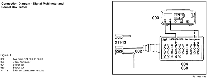
5. Connect socket box and test cable according to connection diagram (Figure 1).
Electrical wiring diagrams :
Electrical Troubleshooting Manual, Models 124 and 201, Starting M.Y. 1984
Electrical Troubleshooting Manual, Model 124, Starting M.Y. 1993
Electrical Troubleshooting Manual, Model 129.

Note concerning Test Connection column in 23:
example
23 5.0 (D.1)
D= connector
1=socket 1

Equipment

Digital multimeter 1) Fluke 23, 83, 88
Sun DMM-5
1) Available through the MBUSA Standard Equipment Program.