Diagnostic Manual, Info./Comm., Volume 1
Electrical Test Program - Test
 |
Test scope |
Test connection
|
Test condition |
Nominal value |
Possible cause/Remedy |
| 1.0 |
Electrolytic capacitor (C3)
Function
|
|
|
|
Ignition: OFF
Radio (A2): ON
Tune radio to weak station in AM band.
Engine: at idle
|
No change in the reception quality. |
Electrolytic capacitor (C3) in right C-pillar. |
| 2.0 |
High frequency wire to radio (A2)
Short circuit
(shielding/signal wire) |

|
|
|
Radio (A2): OFF
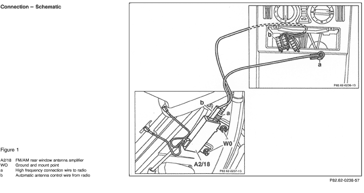
Disconnect connector from radio (A2) and FM/AM rear window antenna amplifier (A2/18) (Figure 1).
|
< 10 
 
|
Wiring. |
| 3.0 |
Radio (A2)
Control voltage |
WO
 |
|
A2/18
 b |
Disconnect connector from (A2/18) (Figure 1).
Radio (A2): ON
|
11 - 14 V |
Wiring,
D.M., Information/Communication, Vol. 1, Radio (RD) - 3.1 >23 |
| 4.0 |
FM/AM rear window antenna amplifier (A2/18) |
A2/18
 |
|
A2
 |
Connect ammeter between A2/18 and automatic antenna control wire from radio (A2) (Figure 1).
Radio (A2): ON
|
52 - 72 mA
|
A2/18,
 5.0 , 5.0 ,
Values are OK: however, there is a poor reception quality:
Replace A2/18 and retest using Function Test  11 , 11 ,
If reception problem continues, replace rear window antenna.
|
| 5.0 |
Ground connection
A2/18 |
 |
|
A2/18 |
Radio (A2): OFF
Note:
Do not loosen mount nuts for A2/18, since mount also functions as ground for A2/18.
|
< 1 
|
Connection (mount) resistance at ground point. |
 |
|


 Printable version


 Printable version