Diagnostic Manual, Body and Accessories,
Volume 1.1
Pneumatic Test Program - Component Locations (CL)
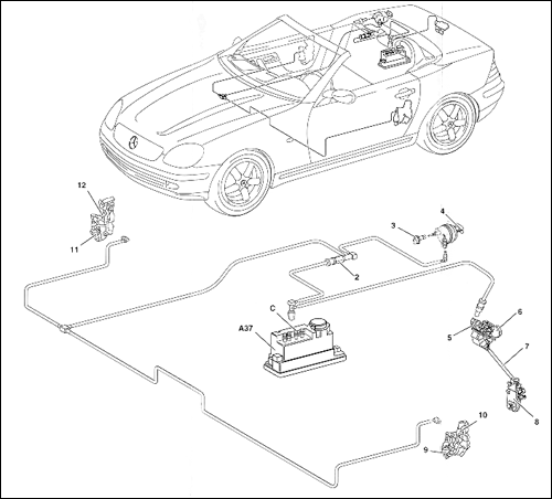
Figure 1
A37 PSE control module, combined function
c Pneumatic connection, CL
2 Pneumatic distributor, CL, frame floor
3 Pneumatic line, fuel tank filler flap sleeve
4 Pneumatic line, fuel tank filler flap actuator
5 Pneumatic line, trunk lid CL actuator
6 Locking cylinder housing
7 Linkage
8 Trunk lid lock
9 Left front door CL actuator
10 Left front door lock
11 Right front door CL actuator
12 Right front door lock
|
|
 |
| |
|
|
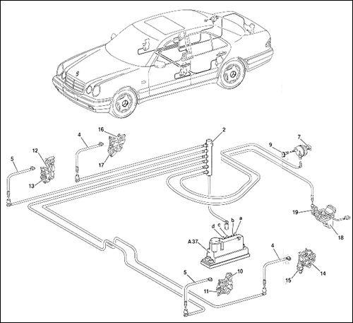
Figure 2
A37 PSE control module, combined function
a Pneumatic connection, OSB
b Pneumatic connection, MVA
c Pneumatic connection, CL/RTR
d Pneumatic connection, RHR
2 Pneumatic distributor, CL
4 Pneumatic line, left and right rear doors
5 Pneumatic line, left and right front doors
7 Fuel tank filler flap actuator
9 Fuel tank filler flap sleeve
10 Left front door lock
11 Left front door CL actuator
12 Right front door lock
13 Right front door CL actuator
14 Left rear door lock
15 Left rear door CL actuator
16 Right rear door lock
17 Right rear door CL actuator
18 Trunk lid lock
19 Trunk lid CL actuator |
|
 |
| |
|
|
|


 Printable
version


