Diagnostic Manual, Body and Accessories,
Volume 1.1
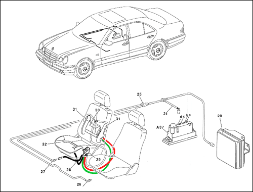
Pneumatic Test Program - Component Locations (OSB)
Figure 1
A37 PSE control module, combined functions
a Pneumatic connection, OSB
b Pneumatic connection, MVA
c Pneumatic connection CL, RTR
d Pneumatic connection,RHR
20 OSB reservoir
21 OSB pneumatic hose (color code: gray)
25 Pneumatic distributor
26 Pneumatidc line, OSB, left front seat
27 Pneumatic line, OSB,right front seat
28 Pneumatic hose set, OSB right front seat
(left front seat is mirror image)
29 OSB control valve, right front seat
(left front seat is mirror image)
30 OSB center insert
(left front seat is mirror image)
31 OSB side bolster insert
(left front seat is mirror image)
32 OSB seat bottom insert
(left front seat is mirror image
RD Red
GN Green
|
|
 |
| |
|
P80-5270-06x |
|


 Printable
version


