Diagnostic Manual, Body and Accessories,
Volume 3
Electrical Test Program - Preparation
for Test
Preliminary work:
Diagnosis - Diagnostic Trouble Code (DTC) Memory  12
12 |
 Fuses OK.
 Battery voltage 11-14 Volts (always
connect battery charger when working on the soft top). Battery voltage 11-14 Volts (always
connect battery charger when working on the soft top).
 RB control module must release
soft top for operation RB control module must release
soft top for operation
(indicator lamp in RB switch should not blink).
If soft top does not release, see DTC 23, in  12.
12.
 In DTC memory, no DTC's (i.e.:19,
21, 24 - 30) which could prevent soft top operation can be stored, these
must be cleared from memory. If a stored DTC cannot be cleared from memory,
repair defect. In DTC memory, no DTC's (i.e.:19,
21, 24 - 30) which could prevent soft top operation can be stored, these
must be cleared from memory. If a stored DTC cannot be cleared from memory,
repair defect.
 Review entire 11.2 section before
performing test. Review entire 11.2 section before
performing test.
Note:
Connect yellow wire from impulse counter scan tool to
Socket 10 Model 129.06 (X11/4, 16-pole)
Socket 21 Model 129.07 (X11/4, 38-pole)
See Connection Diagram - Impulse Counter Scan Tool in section 0.
 CAUTION! CAUTION!
Note regarding limit switch testing:
1. Ignition: OFF
2. Bridge sockets 1 and 3 of connector (X11/12) in passenger footwell
( 21, Figure 1). 21, Figure 1).
3. Ignition: ON
4. Remove bridge.
Electrical wiring diagrams:
Electrical Troubleshooting Manual, Model 129.
 CAUTION! CAUTION!
The test in the next section ( 23)
calls for the connection of the socket box to the power soft top control
module in 3 different ways. Connections are distinguished as connections
made to the power soft top control module connector X, Y or Z. These are
indicated in the test as follows: 23)
calls for the connection of the socket box to the power soft top control
module in 3 different ways. Connections are distinguished as connections
made to the power soft top control module connector X, Y or Z. These are
indicated in the test as follows:
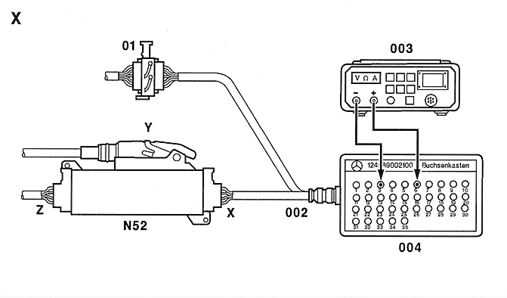
X  indicates that the socket box should
be connected according to Connection Diagram X ( indicates that the socket box should
be connected according to Connection Diagram X ( 22, Figure 1)
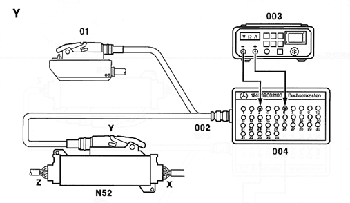
Y  indicates that the socket box should
be connected according to Connection Diagram Y ( indicates that the socket box should
be connected according to Connection Diagram Y ( 22, Figure 2)
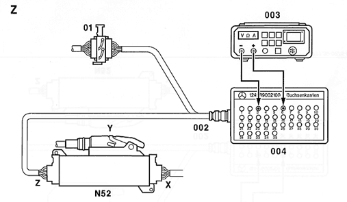
Z  indicates that the socket box should
be connected according to Connection Diagram Z ( indicates that the socket box should
be connected according to Connection Diagram Z ( 22, Figure 3)
Note regarding connecting socket box to soft top control module:
Ignition: OFF
Disconnect connector (X, Y, Z) from control module.
Connect socket box. |
| Test equipment; See MBUSA Standard Service Equipment Program |
| Description |
Brand, model, etc. |
| Digital multimeter |
Fluke models 23, 77 III, 83, 85, 87 |
| Battery charger |
Local purchase |
Connection Diagram - Socket Box with Connector X
Figure 1
01 Connector, 12-pole (vehicle wiring harness)
002 Test cable, 12-pole 129 589 01 63 00
003 Multimeter
004 Socket box
N52 Power soft top control module |
|
 |
| |
|
P77.39-0274-05 |
Connection Diagram - Socket Box with Connector Y
Figure 2
01 Connector, 35-pole (vehicle wiring harness)
002 Test cable, 35-pole 129 589 00 63 00
003 Multimeter
004 Socket box
N52 Power soft top control module |
|
 |
| |
|
P77.39-0275-05 |
Connection Diagram - Socket Box with Connector Z
Figure 3
01 Connector, 12-pole (vehicle wiring harness)
002 Test cable, 12-pole 129 589 01 63 00
003 Multimeter
004 Socket box
N52 Power soft top control module |
|
 |
| |
|
P77.39-0276-05 |
|


 Printable
version


 12
12 Fuses OK.
  CAUTION!
  indicates that the socket box should
be connected according to Connection Diagram X (


