Diagnostic Manual, Body and Accessories,
Volume 3
Electrical Test Program - Survey of Electrical Valve Actuation
|
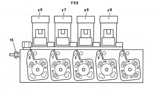
Y55 Left RST Valve Block
(4 connections)
Figure 1
Y55 Left RST valve block (4 connections)
y6 Soft top "open" valve
y7 Soft top "close" valve
y8 Fabric bow "raise" valve
y9 Fabric bow "lower" valve |
|
 |
| |
|
P77.39-0272-05 |
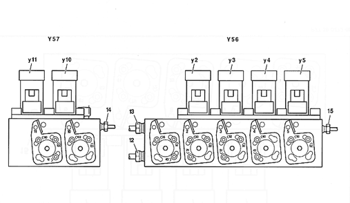
Y56 Right RST Valve
Block
(4 connections)
and
Y57 Roll bar Valve Block
(2 connections)
Figure 2
Y56 Left RST valve block (4 connections)
y2 Rear locks valve
y3 Center locks valve
y4 Front locks valve
y5 Soft top compartment cover valve
Y57 Roll Bar valve block (2 connections)
y10 Roll bar "Lower" valve
y11 Roll bar "raise" valve |
|
 |
| |
|
P77.39-0273-09 |
| Operational Sequence: Soft Top Opening |
|
Left RST valve block
(Y55) |
Hydraulic unit (A7/5) 1) |
RB valve block (Y57) |
Right RST valve block
(Y56) |
| Valves being controlled at time of operational sequence |
y6 |
y7 |
y8 |
y9 |
y1 |
y10 |
y11 |
y4 |
y2 |
y3 |
y5 |
Connection Diagram - Socket box
X ( 22, Figure 1), 22, Figure 1),
Z ( 22, Figure 3) 22, Figure 3) |
X 
10 3 |
X 
10 4 |
X 
10 5 |
X 
10 6 |
X 
10 8 |
X 
10 7 |
Z 
12 8 |
Z 
12 3 |
Z 
12 4 |
Z 
12 5 |
Z 
12 6 |
Lower roll bar,
lower side windows |
0-1 V |
0-1 V |
0-1 V |
0-1 V |
0-1 V |
11-14 V
|
0-1 V |
0-1 V |
0-1 V |
0-1 V |
0-1 V |
| Unlock fabric bow |
0-1 V |
0-1 V |
0-1 V |
0-1 V |
11-14 V |
11-14 V |
0-1 V |
0-1 V |
11-14 V |
0-1 V |
0-1 V |
| Raise fabric bow |
0-1 V |
0-1 V |
11-14 V |
0-1 V |
11-14 V |
11-14 V |
0-1 V |
0-1 V |
11-14 V |
0-1 V |
0-1 V |
| Unlock soft top compartment cover |
0-1 V |
0-1 V |
11-14 V |
0-1 V |
11-14 V |
11-14 V |
0-1 V |
0-1 V |
0-1 V |
11-14 V |
0-1 V |
| Open soft top compartment cover |
0-1 V |
0-1 V |
11-14 V |
0-1 V |
11-14 V |
11-14 V |
0-1 V |
0-1 V |
0-1 V |
11-14 V |
11-14 V |
| Unlock front of soft top |
0-1 V |
0-1 V |
11-14 V |
0-1 V |
11-14 V |
11-14 V |
0-1 V |
11-14 V |
0-1 V |
11-14 V |
11-14 V |
| Open soft top |
11-14 V |
0-1 V |
11-14 V |
0-1 V |
11-14 V |
11-14 V |
0-1 V |
11-14 V |
0-1 V |
11-14 V |
11-14 V |
| Lower soft top into soft top compartment |
11-14 V |
0-1 V |
11-14 V |
0-1 V |
11-14 V |
11-14 V |
0-1 V |
0-1 V |
0-1 V |
11-14 V |
11-14 V |
| Close soft top compartment cover |
11-14 V |
0-1 V |
11-14 V |
0-1 V |
11-14 V |
11-14 V |
0-1 V |
0-1 V |
0-1 V |
11-14 V |
0-1 V |
| Lock soft top compartment cover |
11-14 V |
0-1 V |
0-1 V |
0-1 V |
11-14 V |
11-14 V |
0-1 V |
0-1 V |
0-1 V |
0-1 V |
0-1 V |
Raise roll bar,
raise side windows |
0-1 V |
0-1 V |
0-1 V |
0-1 V |
0-1 V |
11-14 V |
11-14 V |
0-1 V |
0-1 V |
0-1 V |
0-1 V |
| |
|
|
|
|
|
|
|
|
|
|
|
| 1) RST/RB hydraulic unit
main valve (A7/5y1) was deleted as of VIN 1F-083891 |
| Operational Sequence: Closing Soft Top |
|
Left RST valve block
(Y55) |
Hydraulic unit (A7/5) 1) |
RB valve block (Y57) |
Right RST valve block
(Y56) |
| Valves being controlled at time of operational sequence |
y6 |
y7 |
y8 |
y9 |
y1 |
y10 |
y11 |
y4 |
y2 |
y3 |
y5 |
Connection Diagram - Socket box
X ( 22, Figure 3), 22, Figure 3),
Z ( 22, Figure 5) 22, Figure 5) |
X 
10 3 |
X 
10 4 |
X 
10 5 |
X 
10 6 |
X 
10 8 |
X 
10 7 |
Z 
12 8 |
Z 
2 3 |
Z 
12 4 |
Z 
12 5 |
Z 
12 6 |
Lower roll bar,
lower side windows |
0-1 V |
0-1 V |
0-1 V |
0-1 V |
0-1 V |
11-14 V
|
0-1 V |
0-1 V |
0-1 V |
0-1 V |
0-1 V |
| Unlock soft top compartment cover |
0-1 V |
0-1 V |
0-1 V |
0-1 V |
11-14 V |
11-14 V |
0-1 V |
0-1 V |
0-1 V |
11-14 V |
0-1 V |
| Open soft top compartment cover |
0-1 V |
0-1 V |
0-1 V |
0-1 V |
11-14 V |
11-14 V |
0-1 V |
0-1 V |
0-1 V |
11-14 V |
11-14 V |
| Close soft top |
0-1 V |
11-14 V |
11-14 V |
0-1 V |
11-14 V |
11-14 V |
0-1 V |
0-1 V |
0-1 V |
11-14 V |
11-14 V |
| Close soft top (differential operation) |
11-14 V |
11-14 V |
11-14 V |
0-1 V |
11-14 V |
11-14 V |
0-1 V |
0-1 V |
0-1 V |
11-14 V |
11-14 V |
| Lock front of soft top |
0-1 V |
0-1 V |
11-14 V |
0-1 V |
11-14 V |
11-14 V |
0-1 V |
0-1 V |
0-1 V |
11-14 V |
11-14 V |
| Close soft top compartment cover |
0-1 V |
0-1 V |
11-14 V |
0-1 V |
11-14 V |
11-14 V |
0-1 V |
0-1 V |
0-1 V |
11-14 V |
0-1 V |
| Lock soft top compartment cover |
0-1 V |
0-1 V |
11-14 V |
0-1 V |
11-14 V |
11-14 V |
0-1 V |
0-1 V |
0-1 V |
0-1 V |
0-1 V |
| Lower fabric bow |
0-1 V |
0-1 V |
0-1 V |
11-14 V |
11-14 V |
11-14 V |
0-1 V |
0-1 V |
11-14 V |
0-1 V |
0-1 V |
| Lock fabric bow |
0-1 V |
0-1 V |
0-1 V |
11-14 V |
11-14 V |
11-14 V |
0-1 V |
0-1 V |
0-1 V |
0-1 V |
0-1 V |
Raise roll bar,
raise side windows |
0-1 V |
0-1 V |
0-1 V |
0-1 V |
0-1 V |
11-14 V |
11-14 V |
0-1 V |
0-1 V |
0-1 V |
0-1 V |
| 1) RST/RB hydraulic unit
main valve (A7/5y1) was deleted as of VIN 1F-083891 |
| Operational Sequence: Locking Hardtop |
|
Left RST valve block
(Y55) |
Hydraulic unit (A7/5) 1) |
| Valves being controlled at time of operational sequence |
y6 |
y7 |
y8 |
y9 |
y1 |
Connection Diagram - Socket box
X ( 22, Figure 1), 22, Figure 1),
Z ( 22, Figure 3) 22, Figure 3) |
X 
10 3 |
X 
10 4 |
X 
10 5 |
X 
10 6 |
X 
10 8 |
| Rear (lock) |
0-1 V |
0-1 V |
0-1 V |
0-1 V |
11-14 V |
| Front (lock) |
0-1 V |
0-1 V |
0-1 V |
0-1 V |
11-14 V |
| 1) RST/RB hydraulic unit
main valve (A7/5y1) was deleted as of VIN 1F-083891. |
| Operational Sequence: Locking Hardtop |
|
RB valve block (Y57) |
Right RST valve block
(Y56) |
| Valves being controlled at time of operational sequence |
y10 |
y11 |
y4 |
y2 |
y3 |
y5 |
Connection Diagram - Socket box
X ( 22, Figure 1), 22, Figure 1),
Z ( 22, Figure 3) 22, Figure 3) |
X 
10 7 |
Z 
12 8 |
Z 
12 3 |
Z 
12 4 |
Z 
12 5 |
Z 
12 6 |
| Rear (lock) (roll bar "lowered") |
11-14 V |
0-1 V |
0-1 V |
0-1 V |
0-1 V |
0-1 V |
| Rear (lock) (roll bar "raised") |
11-14 V |
11-14 V |
0-1 V |
0-1 V |
0-1 V |
0-1 V |
| Front (lock) (roll bar "lowered") |
11-14 V |
0-1 V |
0-1 V |
0-1 V |
0-1 V |
0-1 V |
| Front (lock) (roll bar "raised") |
11-14 V |
11-14 V |
0-1 V |
0-1 V |
0-1 V |
0-1 V |
| 1) RST/RB hydraulic unit
main valve (A7/5y1) was deleted as of VIN 1F-083891. |
| Operational Sequence: Unlocking Hardtop |
|
Left RST valve block
(Y55) |
Hydraulic unit (A7/5) 1) |
RB valve block (Y57) |
Right RST valve block
(Y56) |
| Valves being controlled at time of operational sequence |
y6 |
y7 |
y8 |
y9 |
y1 |
y10 |
y11 |
y4 |
y2 |
y3 |
y5 |
Connection Diagram - Socket box
X ( 22, Figure 1), 22, Figure 1),
Z ( 22, Figure 3) 22, Figure 3) |
X 
10 3 |
X 
10 4 |
X 
10 5 |
X 
10 6 |
X 
10 8 |
X 
10 7 |
Z 
12 8 |
Z 
12 3 |
Z 
12 4 |
Z 
12 5 |
Z 
12 6 |
| Rear (unlock) |
0-1 V |
0-1 V |
0-1 V |
0-1 V |
11-14 V |
11-14 V |
0-1 V |
11-14 V |
0-1 V |
0-1 V |
0-1 V |
| Front (unlock) |
0-1 V |
0-1 V |
0-1 V |
0-1 V |
11-14 V |
11-14 V |
0-1 V |
0-1 V |
11-14 V |
0-1 V |
0-1 V |
| 1) RST/RB hydraulic unit
main valve (A7/5y1) was deleted as of VIN 1F-083891. |
|


 Printable
version


 22, Figure 1),