|
| Conventional tools, test equipment |
| Description |
Brand, model, etc. |
| Graduated beaker (0.5 liter, 10 ml graduations) |
local purchase |
 |
|
 Risk of personal injury Risk of personal injury
Risk of personal injury (pinching/crushing) while working (loosening or
removal) of pre-tensioned components. Use only approved special tools,
tensioning devices, stops etc. in order to prevent serious injury. Visually
inspect special tools for proper condition/function and possible damage
prior to use. When using spring compressor tools, it is important that
the spindle is not used in a damaged condition, that the threads are clean
and proper. The spring plates are to be straight and not bent in any fashion.
Note the assembly location of each spring plate and that the tightening
nut threads are complatible and clean to the spindle. Do not use
an impact tool to loosen or tighten the spring compressor tool nut. Wear
safety gloves.
Risk of personal injury (pinching/crushing) while working on partially
opened retractable hardtop. The rest mode is the interruption of
the opening or closing sequence of the retractable hardtop, if the switch
(S84) is released while being used to open or close the hardtop.

The rest mode holds the partially opened or closed retractable
hardtop in this position for 7 seconds, thereafter the system is de-pressurized
and depending on the position, the hardtop will come to rest upon itself.
The danger of personal injury (pinching/crushing) exists if the work that
is being carried out without first using the special tools to safely support
the hardtop. Please review and use the special tools as mentioned in  33
33
Risk of personal injury (pinching/crushing) and in extreme cases loss
of limbs or fingers, while working with components that are actuated either
by hand, electrically via motors, hydraulically or pneumatically via connecting
mechanical components, by reaching into moving components or mechanical
units.
It is important that limbs, fingers and body parts be kept away from
the operating areas of the moving components, especially if the components
are actuated via the HHT or directly via circuit 30. Ensure that the test
cables are of proper length, to prevent entanglement.
Keep clear of the retractable hardtop frame and linkage, upper part of
the winshield and trunk lid during any retractrable hardtop operation.
Before begining the test, check the oil level in the hydraulic unit reservoir
and top up if needed (refer to the Maintenance Manual).
In order to make accurate visual inspection for oil loss from the hydraulic
system, the trim panels covering the hydraulic components must be removed.
The front latch can be locked or unlocked using the special tool provided
with the vehicle for manual hardtop operation. The trunk can be unlocked
using pull cables (refer to Owners Manual).
The hydraulic circuits and components for each operation of the hardtop
can be tested separately.
Lastly, it is important to wear safety gloves when performing the tests.
Notes for Hydraulic Test:
The following jobs are the same for all test steps:
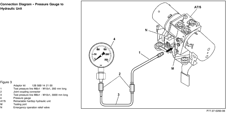
A. Connection of test equipment to hydraulic unit (Figure 3).
B. Test the hydraulic cylinders only at the piston's end position (prevents
movement).
C. If the hydraulic lines need to be disconnected during pressure tests,
the appropriate end position of the hydraulic cylinder must be first ensured.
D. All necessary hardtop positions can be achieved by pressing the retractable
hardtop switch (S84) or by pulling the hardtop manually (Ignition: OFF).
 In order to move the retractable
hardtop manually, the emergency In order to move the retractable
hardtop manually, the emergency
operation relief valve on the hydraulic unit must be open all the way
to a stop position using the allen wrench provided with the vehicle, refer
to "N" in Figure 3). The emergency operation relief valve
must be then closed (tightening torque approx.: 3 Nm).

The emergency operation relief valve can only be open with retractable
hardtop closed or in open/stored position and with the ignition switch
in OFF. If this is not adhered to, the seal on the valve could be damaged,
which would in turn hinder building up the operating pressure in the hydraulic
system.

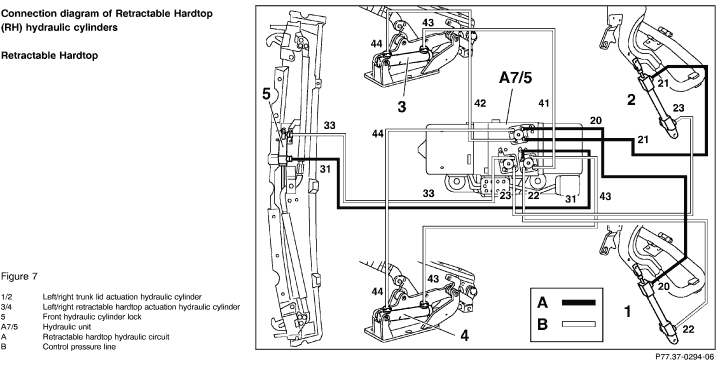
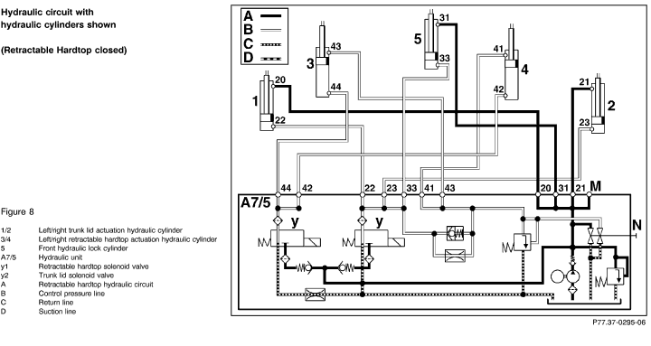
The hydraulic cylinders (3 and 4, Figure 8) will lose all the pressure
during manual movement of the retractable hardtop. If the hardtop is in
the closed position, the retractable hardtop switch (S84) must be pressed
toward front (close) for 5 sec. in order to build up the pressure in the
cylinders again.
If the hydraulic cylinders are without hydraulic pressure and the retractable
hardtop switch (S84) is pressed towards back (open position), the retractable
hardtop will open rapidly. This could cause damage to the hardtop itself
and to the components in the trunk/storage area.
Releasing the test pressure.
If the retractable hardtop comes to the end position (open/stored or closed)
by pressing the retractable hardtop switch, the hydraulic pressure must
be released from the system before disconnecting any hydraulic lines.
To achieve that, the ignition switch must be in the OFF position and the
relief valve on the hydraulic unit ("N", Figure 3) must be open
all the way to the stop position. The pressure should drop in a short
time, as observed on the pressure gauge. Place a shop towel around the
hydraulic lines to be disconnected to avoid hydraulic oil spills when
removing hydraulic lines. Additionally the ports must be plugged off using
the necessary plug. The removed hydraulic lines should be placed in a
container as well.
 For plugging the entry ports
on the hydraulic unit during the For plugging the entry ports
on the hydraulic unit during the
pressure tests, the plugs - part number 129 589 00 91 01 must be used.
 To use the pressure gauge after
setting the hardtop to the desired To use the pressure gauge after
setting the hardtop to the desired
position at the test steps  2.0,
3.0, 5.0, 5.1, 5.2, 7.0, 7.1, 8.0, 8.1, 8.2, 8.3, 8.4, the trunk lid must
be open via turnk lid lock and the rotary latch moved (using a small screwdriver)
to a locked position. Before closing the lid, the rotary latch
open position must be restored by pressing the lock button. 2.0,
3.0, 5.0, 5.1, 5.2, 7.0, 7.1, 8.0, 8.1, 8.2, 8.3, 8.4, the trunk lid must
be open via turnk lid lock and the rotary latch moved (using a small screwdriver)
to a locked position. Before closing the lid, the rotary latch
open position must be restored by pressing the lock button.
If hydraulic components need to be replaced, the disconnected hydraulic
lines must be plugged with plug 129 589 00 91 07, while the ports on hydraulic
unit must be plugged immediately using plug 129 589 00 91 11 to
prevent the possible entry of dirt.
|
 |
 |
 |
 |
 |
 |
 |
 |
 |
Test scope |
Test connection |
Test condition |
Nominal value |
Possible cause/Remedy |
| 1.0 |
|
Checking retractable hardtop hydraulic
unit (A7/5)
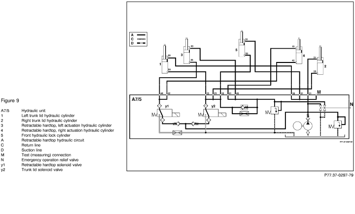
(Figure 9) |
Connect pressure gauge according to connection diagram (Figure 3).
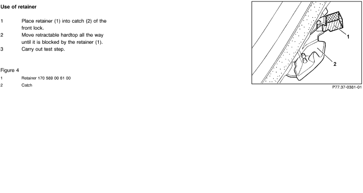
Block retractable hardtop at the front latch with the retainer (part number 170 589 00 61 00). Refer to Figure 4 - Use of retainer. |
Starting point:
Retractable hardtop rests on the front latches, trunk lid pivoted towards rear.
Ignition: ON
Press and hold retractable hardtop switch (S84) for 5 sec. in close position (towards front).
Read test pressure:
|
180 - 200 bar |
Check emergency operation relief valve (N)
Tightening torque: 3 Nm
<180 bar:
Replace retractable hardtop hydraulic unit (A7/5).
Nominal value O. K.
 2.0 2.0 |
 |
 |
 |
Test scope |
Test connection |
Test condition |
Nominal value |
Possible cause/Remedy |
| 2.0 |
|
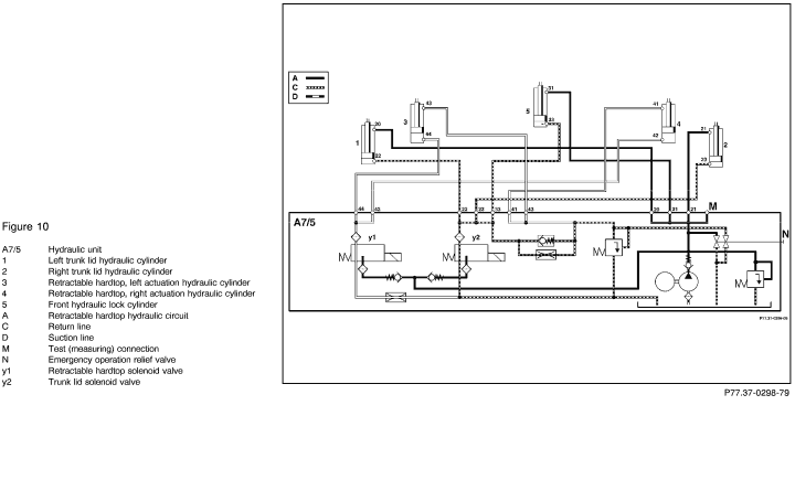
Hydraulic circuit pressure test
(Figure 10) |
Connect pressure gauge according to connection diagram (Figure 3).
N10-3

 + +    22 22 |
Starting point:
Retractable hardtop completely open.
Trunk lid open, rotary latch on trunk lid lock locked.

Disconnect connector A on combination control module N10-3.
Bridge + terminal and pin 22 on the control module connector with test cable 124 589 37 63 00
Set the bridge for 5 sec.
Read test pressure while the retractable hardtop hydraulic unit runs.
|
180 - 200 bar |
< 180 bar:
 4.0
4.0
Nominal values O. K.:
 3.0
3.0 |
 |
 |
 |
Test scope |
Test connection |
Test condition |
Nominal value |
Possible cause/Remedy |
| 3.0 |
|
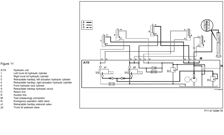
Checking fluid volume output of hydraulic unit (A7/5)
(Figure 11)

Room temperature not to be <70° F (18° C). |
Disconnect hydraulic line number 21 from hydraulic unit. Seal connection with plug
129 589 00 91 07.
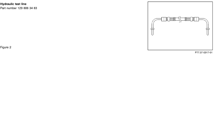
Connect test line part number 129 806 34 83 to the output port of line number 21 on the hydraulic unit and insert that hydraulic line into a graduated beaker. |
Starting point:
Retractable hardtop completely open, trunk lid open, rotary latch on the trunk lid lock locked
Ignition: ON
Press and hold retractable hardtop switch in open position for 15 sec.
Read and note hydraulic fluid volume output in graduated beaker: |
>0.10 liter
(100 ml). |
<0.10 liter
Replace retractable hardtop hydraulic unit (A7/5). |
 |
 |
 |
Test scope |
Test connection |
Test condition |
Nominal value |
Possible cause/Remedy |
| 4.0 |
|
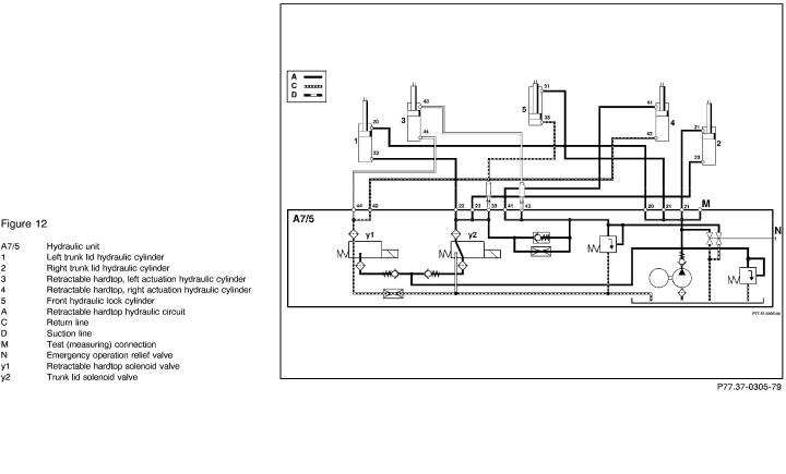
Checking retractable hardtop movement hydraulic cylinder (pushing rod side)
(3, Figure 12)
Complaint:
Retractable hardtop does not open or opens slowly. |
Connect pressure gauge according to connection diagram (Figure 3).
Disconnect hydraulic lines numbers 33 and 43 from hydraulic unit. Seal connection with plug
129 589 00 91 01.

Release hydraulic working pressure (refer to "Notes for Hydraulic Test")
N10-3

 + +    22 22
 + +    25 25
|
Movement sequence:
Retractable hardtop opens
Starting point:
Retractable hardtop closed, front latch locked (using allen wrench), trunk lid pivoted towards rear.

Disconnect connector A on combination control module N10-3.
Bridge the control module connector with test cable 124 589 37 63 00 as shown
Set bridge for 5 seconds.
Read test pressure while the retractable hardtop hydraulic unit runs |
180 - 200 bar |
Nominal values O.K:
Retractable hardtop actuation hydraulic cylinder (3, Figure 12) leaking.
Replace hydraulic cylinder.
<180 bar:
 4.1 4.1 |
 |
 |
 |
Test scope |
Test connection |
Test condition |
Nominal value |
Possible cause/Remedy |
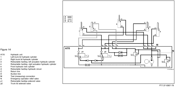
| 4.1 |
|
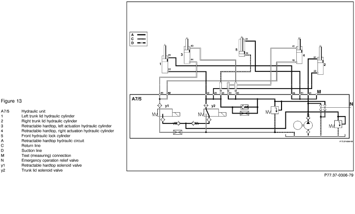
Checking retractable hardtop actuation hydraulic cylinder (pushing rod side)
(4, Figure 13)
Complaint:
Retractable hardtop does not open or opens slowly. |
Connect pressure gauge according to connection diagram (Figure 3).
Disconnect hydraulic line number 41 from hydraulic unit. Seal connection with plug 129 589 00 91 01.
Leave hydraulic lines 33 and 43 disconnected.
N10-3

 + +    22 22
 + +    25 25
|
Retractable hardtop closed, front latch locked, trunk lid pivoted towards rear

Disconnect connector A on combination control module N10-3.
Bridge the control module connector with test cable 124 589 37 63 00 as shown
Set the bridge for 5 sec.
Read test pressure while the retractable hardtop hydraulic unit runs |
180 - 200 bar |
Nominal values O.K:
Retractable hardtop actuation hydraulic cylinder (4, Figure 13) leaking.
Replace hydraulic cylinder.
<180 bar:
 1.0 1.0
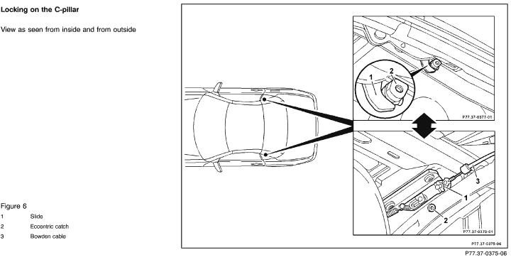
If the retractable hardtop does not open, check the locking devices on C-pillars for proper function see Figure 6.
For adjustment instructions refer to job number:
AR77.33-3470G |
 |
 |
 |
 |
Test scope |
Test connection |
Test condition |
Nominal value |
Possible cause/Remedy |
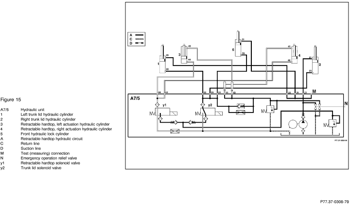
| 4.3 |
|
Checking retractable hardtop actuation
hydraulic cylinder (pushing rod side)
(4, Figure 15)
Complaint:
Trunk lid does not close or closes slowly. |
Connect pressure gauge according
to connection diagram (Figure 3).
Disconnect hydraulic line number 41 from hydraulic unit. Seal connection with plug 129 589 00 91 01.
Leave hydraulic line number 43 disconnected.
N10-3

 + +    22 22
 + +    25 25 |
Retractable hard top front latch
open, trunk lid pivoted to rear, retractable hard top open

Disconnect connector A on combination control module N10-3.
Bridge the control module connector with test cable 124 589 37 63 00 as shown
Set the bridge for 5 sec.
Read test pressure while the retractable hardtop hydraulic unit runs
|
180 - 200 bar |
Nominal values O. K.:
Retractable hardtop actuation hydraulic cylinder (4, Figure 15) leaking.
Replace hydraulic cylinder.
<180 bar:
 1.0 1.0
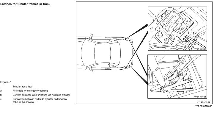
If the trunk lid does not open, check the latches for tubular frames in the trunk (Figure 5).
Check adjustment of the bowden cables, for adjustment instructions refer to job number:
AR77.33-3470G |
 |
 |
 |
Test scope |
Test connection |
Test condition |
Nominal value |
Possible cause/Remedy |
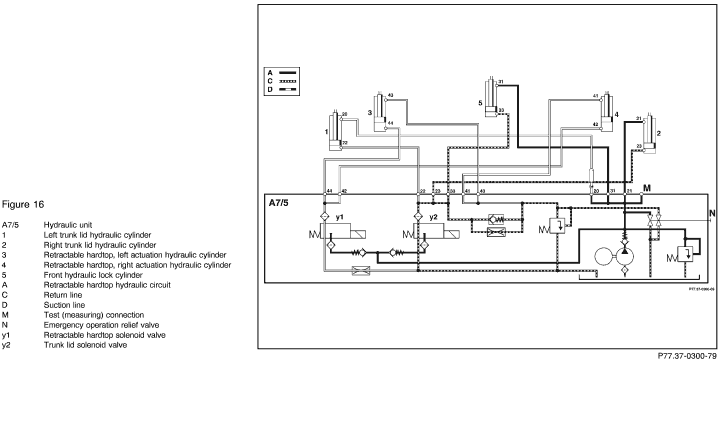
| 5.0 |
|
Checking trunk lid actuation hydraulic cylinder (pushing rod side)
(1, Figure 16)
Complaint:
Trunk lid does not close or closes slowly. |
Connect pressure gauge according to connection diagram (Figure 3).
Disconnect hydraulic line number 20 from hydraulic unit. Seal connection with plug 129 589 00 91 01.
|
Starting point:
Retractable hardtop fully open, trunk lid open, rotary latch on trunk lid lock locked.
Ignition: ON
Press retractable hardtop switch (S84) to open position for 5 sec.
Read test pressure while depressing the switch
|
180 - 200 bar |
Nominal values O. K.:
Trunk lid actuating hydraulic cylinder (1, Figure 16) leaking.
Replace hydraulic cylinder.
<180 bar:
 5.1 5.1 |
 |
 |
 |
Test scope |
Test connection |
Test condition |
Nominal value |
Possible cause/Remedy |
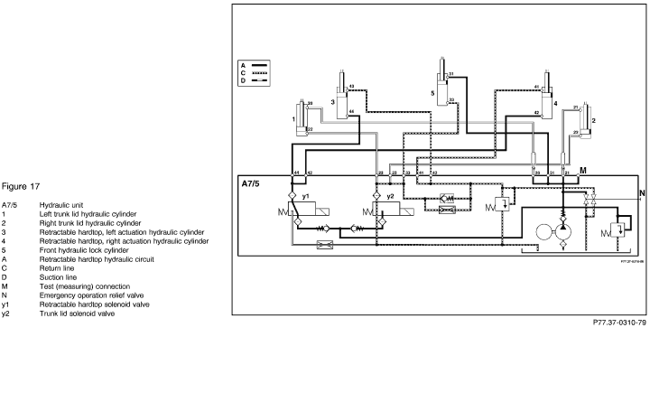
| 5.1 |
|
Checking trunk lid actuation hydraulic cylinder (pushing rod side)
(2, Figure 17)
Complaint:
Trunk lid does not close or closes slowly. |
Connect pressure gauge according to connection diagram (Figure 3).
Disconnect hydraulic line number 21 from hydraulic unit. Seal connection with plug 129 589 00 91 01.
Leave hydraulic line number 20 disconnected. |
Retractable hardtop fully open, trunk lid fully open, rotary latch on trunk lid lock locked.
Ignition: ON
Press retractable hardtop switch (S84) to open position for 5 sec.
Read test pressure while depressing the switch
|
180 - 200 bar |
Nominal values O. K.:
Trunk lid actuation hydraulic cylinder (2, Figure 17) leaking.
Replace hydraulic cylinder.
<180 bar:
 6.0 6.0 |
 |
 |
 |
Test scope |
Test connection |
Test condition |
Nominal value |
Possible cause/Remedy |
| 5.2 |
|
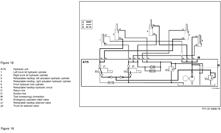
Checking trunk lid actuation hydraulic cylinder (pushing rod side)
(1, Figure 18)
Complaint:
Front latch does not lock. |
Connect pressure gauge according to connection diagram (Figure 3).
Disconnect hydraulic line number 20 from hydraulic unit. Seal connection with plug 129 589 00 91 01.
|
Starting point: Retractable hardtop closed, front latch open, trunk lid locked into latches within trunk, trunk lid open, rotary latch on trunk lid lock locked.
Ignition: ON
Press retractable hardtop switch (S84) to close position for 5 sec.
Read test pressure while depressing the switch |
180 - 200 bar |
Nominal values O. K.:
Trunk lid actuation hydraulic cylinder (1, Figure 18) leaking.
Replace hydraulic cylinder.
<180 bar:
 5.3 5.3 |
 |
 |
 |
Test scope |
Test connection |
Test condition |
Nominal value |
Possible cause/Remedy |
| 5.3 |
|
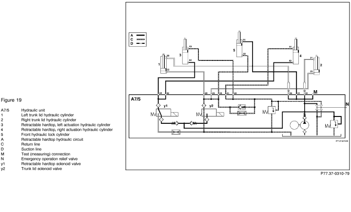
Checking trunk lid actuation hydraulic cylinder (pushing rod side)
(2, Figure 19)
Complaint:
Front latch does not lock. |
Connect pressure gauge according to connection diagram (Figure 3).
Disconnect hydraulic line number 21 from hydraulic unit. Seal connection with plug 129 589 00 91 01.
Leave hydraulic line number 20 disconnected. |
Retractable hardtop closed, front latch open, trunk lid locked into latches within trunk, trunk lid open, rotary latch on trunk lid lock locked.
Ignition: ON
Press retractable hardtop switch (S84) to close position for 5 sec.
Read test pressure while depressing the switch |
180 - 200 bar |
Nominal values O. K.:
Trunk lid actuation hydraulic cylinder (2, Figure 19) leaking.
Replace hydraulic cylinder.
<180 bar:
 7.0 7.0 |
 |
 |
 |
Test scope |
Test connection |
Test condition |
Nominal value |
Possible cause/Remedy |
| 6.0 |
|
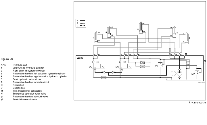
Checking front hydraulic lock cylinder (pushing rod side)
(5, Figure 20)
Complaint:
Trunk lid does not close or closes slowly. |
Connect pressure gauge according to connection diagram (Figure 3).
Disconnect hydraulic line number 31 from hydraulic unit. Seal connection with plug 129 589 00 91 01.
Leave the hydraulic lines numbers 20 and 21 disconnected. |
Retractable hardtop fully open, trunk lid open rotary latch on the trunk lid lock locked.
Ignition: ON
Press retractable hardtop switch (S84) to open position for 5 sec.
Read test pressure while depressing the switch.
|
180 - 200 bar |
Nominal values O. K.:
Front hydraulic lock cylinder
(5, Figure 20) leaking.
Replace hydraulic cylinder.
<180 bar:
 1.0 1.0 |
 |
 |
 |
Test scope |
Test connection |
Test condition |
Nominal value |
Possible cause/Remedy |
| 6.1 |
|
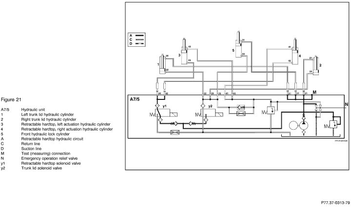
Checking front hydraulic lock cylinder (pushing rod side)
(5, Figure 21)
Complaint:
Front latch lock does not lock. |
Connect pressure gauge according to connection diagram (Figure 3).
Disconnect hydraulic line number 31 from hydraulic unit. Seal connection with plug 129 589 00 91 01.
Leave the hydraulic lines numbers 20 , 21, 42 and 44 disconnected. |
Retractable hardtop closed, front lock open, trunk lid locked into its latches in the trunk, trunk lid open, rotary latch in trunk lid lock locked.
Ignition: ON
Press retractable hardtop switch (S84) to close position for 5 sec.
Read test pressure while depressing the switch |
180 - 200 bar |
Nominal values O. K.:
Front hydraulic lock cylinder
(5, Figure 21) leaking.
Replace hydraulic cylinder.
<180 bar:
 1.0 1.0 |
 |
 |
 |
Test scope |
Test connection |
Test condition |
Nominal value |
Possible cause/Remedy |
| 7.0 |
|
Checking retractable hardtop actuation
hydraulic cylinder (piston side)
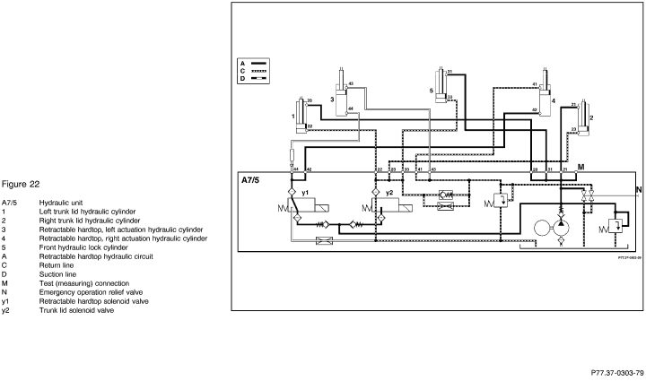
(3, Figure 22)
Complaint:
Trunk lid does not close or closes slowly. |
Connect pressure gauge according
to connection diagram (Figure 3).
Disconnect hydraulic line number 44 from hydraulic unit. Seal connection with plug 129 589 00 91 01.
N10-3

 + +    22 22
 + +    24 24
|
Starting point: Retractable
hardtop fully closed, trunk lid open, rotary latch in trunk lid lock locked.

Disconnect connector A on combination control module N10-3.
Bridge the control module connector with test cable 124 589 37 63 00 as shown.
Set the bridge for 5 sec.
Read test pressure while the retractable hardtop hydraulic unit runs
|
180 - 200 bar |
Nominal values O. K.:
Retractable hardtop actuation hydraulic cylinder (3, Figure 22) leaking.
Replace hydraulic cylinder.
<180 bar:
 7.1 7.1 |
 |
 |
 |
Test scope |
Test connection |
Test condition |
Nominal value |
Possible cause/Remedy |
| 7.1 |
|
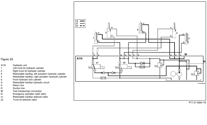
Checking retractable hardtop actuation hydraulic cylinder (piston side)
(4, Figure 23)
Complaint:
Trunk lid does not close or closes slowly. |
Connect pressure gauge according to connection diagram (Figure 3).
Disconnect hydraulic line number 42 from hydraulic unit. Seal connection with plug 129 589 00 91 01.
Leave hydraulic line number 44 disconnected. |
Retractable hardtop fully closed, trunk lid open, rotary latch on trunk lid lock locked.

Disconnect connector A on combination control module N10-3.
Bridge the control module connector with test cable 124 589 37 63 00 as shown.
Set the bridge for 5 sec.
Read test pressure while the retractable hardtop hydraulic unit runs |
180 - 200 bar |
Nominal values O. K.:
Retractable hardtop actuation hydraulic cylinder (4, Figure 23) leaking.
Replace hydraulic cylinder.
<180 bar:
 5.0 5.0 |
 |
 |
 |
Test scope |
Test connection |
Test condition |
Nominal value |
Possible cause/Remedy |
| 7.2 |
|
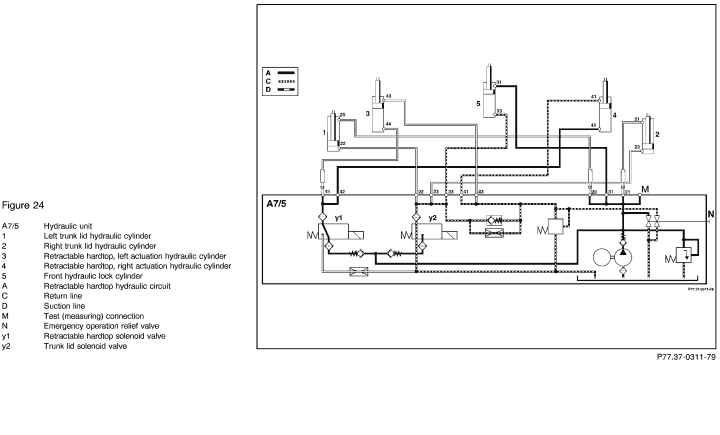
Checking retractable hardtop actuation hydraulic cylinder (piston side)
(3, Figure 24)
Complaint:
Front latch lock does not lock. |
Connect pressure gauge according to connection diagram (Figure 3).
Disconnect hydraulic line number 44 from hydraulic unit. Seal connection with plug 129 589 00 91 01.
Leave hydraulic lines numbers 20 and 21 disconnected. |
Retractable hardtop closed, front latch lock open, trunk lid locked into its latches in the trunk, trunk lid open, rotary latch on trunk lid lock locked.
Ignition: ON
Press retractable hardtop switch (S84) to close position for 5 sec.
Read test pressure while depressing the switch
|
180 - 200 bar |
Nominal values O. K.:
Retractable hardtop actuation hydraulic cylinder (3, Figure 24) leaking.
Replace hydraulic cylinder.
<180 bar:
 7.3 7.3 |
 |
 |
 |
Test scope |
Test connection |
Test condition |
Nominal value |
Possible cause/Remedy |
| 7.3 |
|
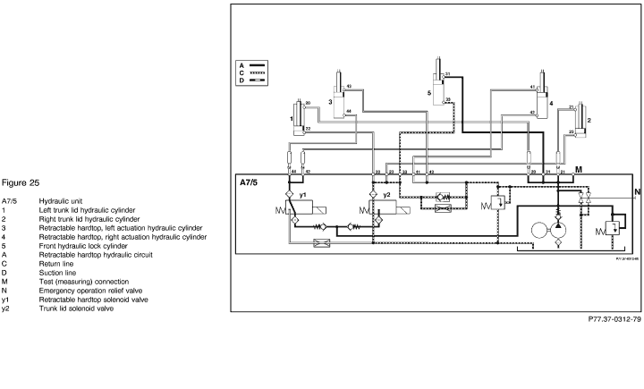
Checking retractable hardtop actuation hydraulic cylinder (piston side)
(4, Figure 25)
Complaint:
Front latch lock does not lock. |
Connect pressure gauge according to connection diagram (Figure 3).
Disconnect hydraulic line number 42 from hydraulic unit. Seal connection with plug 129 589 00 91 01.
Leave hydraulic lines numbers 20, 21 and 44 disconnected. |
Retractable hardtop closed, front latch lock open, trunk lid locked into its latches in the trunk, trunk lid open, rotary latch on trunk lid lock locked.
Ignition: ON
Press retractable hardtop switch (S84) to close position for 5 sec.
Read test pressure while depressing the switch |
180 - 200 bar |
Nominal values O. K.:
Retractable hardtop actuation hydraulic cylinder (4, Figure 25) leaking.
Replace hydraulic cylinder.
<180 bar:
 6.0 6.0 |
|


 Printable
version


 Printable
version