Diagnostic Manual, Chassis and Drivetrain,
Volume 2
Electrical Test Program - Preparation for Test
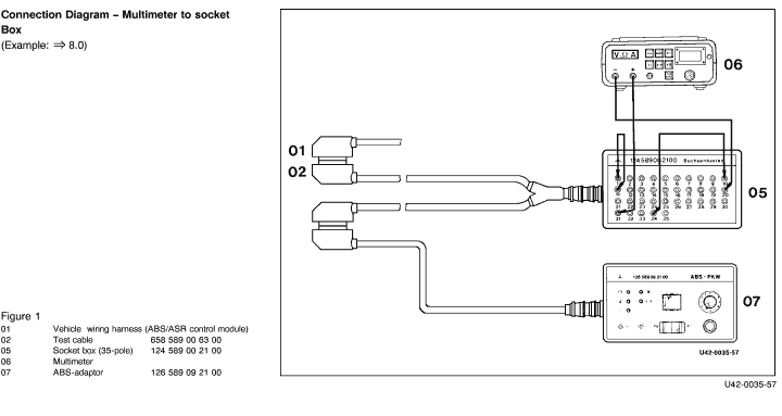
1. Socket box sockets 1  11 and 10 34 must be bridged during the entire ABS/ASR test. 11 and 10 34 must be bridged during the entire ABS/ASR test.
2. In test steps which include "Ignition: ON", the LED  must illuminate i.e battery voltage ok. must illuminate i.e battery voltage ok.
3. Observe the ABS and ASR malfunction indicator lamps as well as the ASR function indicator only if required to do so in the "Nominal value" column of a particular test step.
4. Always perform  38.0 and 39.0 in sequence. 38.0 and 39.0 in sequence.
5. After 39.0 (reservoir full), correct in brake fluid reservoir.
Electrical wiring diagrams :
see "Electrical Troubleshooting Manual, Model 129, Volume 1, Group 42".
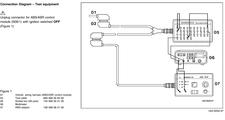
 Never drive the vehicle with the ABS-adaptor (07) connected! Never drive the vehicle with the ABS-adaptor (07) connected!
|
Conventional tools, test equipment
| Description |
Brand, model, etc. |
| Multimeter 1) |
Fluke models 23, 83, 85, 87 |
| 1) Available through the MBUSA Standard Equipment Program. |
|


 Printable version