Diagnostic Manual, Chassis and Drivetrain,
Volume 2
Diagnosis - Diagnostic Trouble Code (DTC) Memory
Test Preparation for DTC Readout
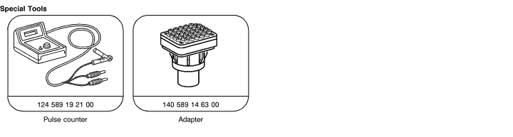
1. Connect impulse counter scan tool or Hand-Held Tester to data link connector (X11/4) as shown in section 0.
Note:
Connect yellow wire from impulse counter scan tool as follows:
ABS control module (N30) socket 6
Base module (N16/1) socket 8
2. Ignition: ON.
3. Read DTC memory of ABS control module (N30), and base module (N16/1). |
Equipment
| Hand-Held Tester (HHT) |
see applicable Service Information in groups 58
and 99 |
| Diagnostic trouble code (DTC) |
Possible cause |
Test step/Remedy 1) |
 |
 |
|
|
 |
 |
No faults recognized. In case of complaint: |
 23 (entire test) 23 (entire test) |
 |
 |
Left front axle vehicle speed sensor (L6/1), open circuit |
23 10.0 10.0 |
 |
|
Right front axle vehicle speed sensor (L6/2), open circuit |
23 12.0 |
 |
|
Rear axle vehicle speed sensor (L6), open circuit |
23 14.0 |
 |
|
Left front axle solenoid valve (A7y1) |
23 16.0 |
 |
|
Right front axle solenoid valve (A7y2) |
23 17.0 |
 |
|
Rear axle solenoid valve (A7y3) |
23 18.0 |
| |
|
Return pump (A7m1) or return pump relay (A7k2) |
23 6.0 |
| |
|
Solenoid valve relay (A7k1) |
23 5.0 |
|
|
Models 140.04/05: Master cylinder switchover valve (Y61) |
23 7.0 |
| |
|
Brake lamp switch (S9/1) |
23 9.0 |
|
|
Models 140.04/05: Lateral acceleration sensor (B24/2) |
23 8.0 |
 |
|
ABS control module (N30) |
N30 |
|
|
Vehicle speed sensors (L6, L6/1, L6/2), implausible signal 2) |
23 10.0
23 12.0
23 14.0
Visual inspection |
|
|
Solenoid valve relay (A7k1) |
23 5.0 |
| |
|
Left front axle vehicle speed sensor (L6/1), implausible signal 2) |
23 10.0 |
|
|
Right front axle vehicle speed sensor (L6/2), implausible signal 2) |
23 12.0 |
|
|
Rear axle vehicle speed sensor (L6), implausible signal 2) |
23 14.0 |
 |
|
Models 140.04/05: Lateral acceleration sensor (B24/2), implausible signal |
23 8.0 |
1) Observe Preparation for Test, see 22.
2) Incorrect number of rotor teeth, dirty or damaged, incorrect rear axle ratio, tires or wheels. |
|


 Printable version