Test step
|
DTC |
Test scope
|
Test connection
|
Test condition
|
Nominal value
|
Possible cause/Remedy
|
| 1.0 |
  |
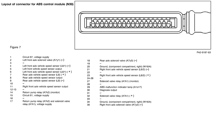
ABS control module (N30)
Voltage supply
Circuit 87 E
|
20 
34 |
N30

|
 1 1 |
Ignition: ON
|
11 - 14 V |
 1.1, 1.1,
Wiring,
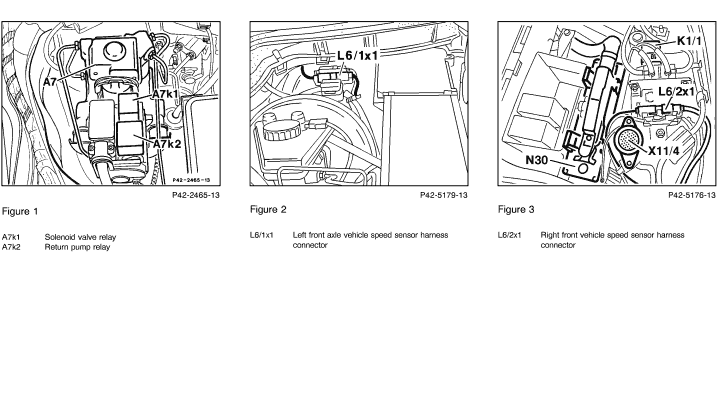
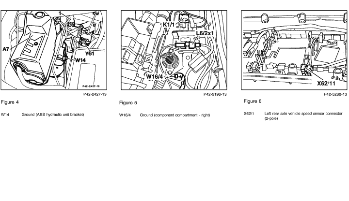
Ground, (component compartment, W16/4, Figure 5).
|
| 1.1 |
|
Voltage supply from overvoltage protection relay module (K1/1) |
W16/4 (Figure 5)
|
|
N30
 1 |
Ignition: ON |
11 - 14 V |
Fuse at K1/1,
Wiring,
K1/1. |
| 2.0 |
|
ABS malfunction indicator lamp (MIL) (A1e17) |
|
N30
|
29
|
Ignition: ON
Engine: At idle
|
< 2 V
A1e17: ON
10 - 14 V
A1e17: OFF
|
Wiring,
ABS MIL (A1e17),
2.1
Fault stored, Read DTC
memory:  11, 11,
Wiring,
ABS control module (N30).
|
| 2.1 |
|
Diode in solenoid valve (A7k1) |
|
|
|
Engine: OFF
Disconnect ABS control module (N30).
Ignition: ON
Engine: At idle
|
A1e17: ON
A1e17: ON |
Wiring,
A7k1.
|
| 3.0 |
|
Diagnosis output |
20
|
N30
|
30
|
Ignition: ON |
10 - 14 V
|
Wiring,
ABS control module (N30).
|
| 4.0 |
|
Circuit 61 Voltage |
20
|
N30
|
15
|
Ignition: ON
Engine: Start |
< 1 V
11 - 14 V
|
Wiring,
Generator (G2).
|
| 5.0 |
|
Solenoid valve relay (A7k1)
Control
Monitor
|
27
20
|
|
17
32
|
Ignition: ON |
10 - 14 V
11 - 14 V |
DTC stored, see 11(clear DTC),
5.1 to 5.3
Wiring.
|
| 5.1 |
|
Voltage supply |
20
|
N30
|
17
|
Ignition: ON |
11 - 14 V
|
Wiring,
1.0,
ABS control module (N30). |
| 5.2 |
|
Coil resistance |
27
|
N30

|
17
|
Ignition: OFF
Disconnect ABS control module (N30).
|
40 - 80 
|
Wiring,
Solenoid valve relay (A7k1). |
| 5.3 |
|
Operational contact |
W14 (Figure 4)
|
|
N30
32 |
Ignition: OFF
Disconnect N30.
|
< 1 |
Wiring,
Solenoid valve relay (A7k1), |
| 6.0 |
 |
Return pump relay (A7k2)
Voltage supply |
20 |
N30
|
41
|
Ignition: ON
|
11 - 14 V
|
Wiring,
6.1,
Return pump (A7m1). |
| 6.1 |
|
Coil resistance |
17
|
N30
|
28
|
Ignition: OFF
Disconnect N30.
|
40 - 80
|
Wiring,
Return pump (A7k2, Figure 1). |
| 7.0 |


 |
Left front axle vehicle speed sensor (L6/1)
|
4
|
N30
 |
6
|
Lift front of vehicle.
Ignition: ON
Rotate left front wheel. |
> 0.1 V~ |
7.1,
7.2
|
| 7.1 |
|
Insulation resistance |
20
|
N30
|
6
|
Ignition: OFF
Disconnect N30.
|
> 20 k |
Wiring. |
| 7.2 |
|
Internal resistance |
4
|
N30
|
6
|
Ignition: OFF
Disconnect (N30) from socket box.
|
0.8 - 3.7 k |
Wiring,
L6/1. |
| 8.0 |
|
Left front axle vehicle speed sensor output
|
20
|
N30
|
5
|
Lift front of vehicle.
Ignition: ON
Rotate left front wheel. |
> 3 V~ |
Wiring,
7.0,
8.1
|
| 8.1 |
|
Circuit loading from connected control modules
|
20
|
N30
|
5
|
Ignition: OFF
Disconnect N30.
|
> 5 k |
Wiring,
Connected control modules
(A1, A2, N4/1, N4/2, N22).
|
9.0
|

|
Right front axle vehicle speed sensor (L6/2) |
21
|
N30
|
23
|
Lift front of vehicle.
Ignition: ON
Rotate right front wheel. |
> 0.1 V~
|
9.1,
9.2 |
| 9.1 |
|
Insulation resistance |
20
|
N30
|
23
|
Ignition: OFF
Disconnect N30.
|
> 20 k |
Wiring.
|
| 9.2 |
|
Internal resistance |
21
|
N30
|
23
|
Ignition: OFF
Disconnect N30.
|
0.8 - 3.7 k
|
Wiring,
L6/2.
|
| 10.0 |
|
Right front axle vehicle speed sensor output |
20
|
N30
|
11
|
Lift front of vehicle.
Ignition: ON
Rotate right front wheel.
|
> 3 V~
|
Wiring,
9.0,
10.1 |
| 10.1 |
|
Circuit loading from connected control modules |
20
|
N30
|
11
|
Ignition: OFF
Disconnect N30.
|
> 5 k
|
Wiring,
Connected control modules (N30/2). |
11.0
|

|
Rear axle vehicle speed sensor (L6)
|
9
|
N30
|
7
|
Lift rear of vehicle.
Ignition: ON
Rotate a rear wheel
|
> 0.1 V~
|
11.1,
11.2 |
| 11.1 |
|
Insulation resistance |
20
|
N30
|
7
|
Ignition: OFF
Disconnect (N30).
|
>20 k |
Wiring.
|
| 11.2 |
|
Internal resistance
|
9
|
N30
|
7
|
Ignition: OFF
Disconnect N30.
|
0.6 - 3.2 k |
Wiring,
L6. |
| 12.0 |
|
Rear axle vehicle speed sensor output
|
20
|
N30
|
8
|
Lift rear of vehicle.
Ignition: ON
Rotate a rear wheel.
|
> 3 V~
|
11.0,
12.1 |
| 12.1 |
|
Circuit loading from connected control modules
|
20
|
N30
|
8
|
Disconnect N30.
Ignition: ON
Rotate a rear wheel.
|
>5 k
|
Wiring,
Connected control modules
(N3/4, N4/2, N30/2). |
| 13.0 |
|
Left front axle solenoid
valve (A7y1)
Internal resistance |
2
|
N30
|
32
|
Ignition: OFF
Disconnect N30. |
0.7 - 2.2 k |
Wiring,
ABS hydraulic unit (A7).
|
| 14.0 |
|
Right front axle solenoid valve (A7y2)
Internal resistance |
35
|
N30
|
32
|
Ignition: OFF
Disconnect N30. |
0.7 - 2.2 k |
Wiring,
ABS hydraulic unit (A7).
|
| 15.0 |
 |
Rear axle vehicle solenoid valve (A7y3)
Internal resistance |
18
|
N30
|
32
|
Ignition: OFF
Disconnect N30. |
0.7 - 2.2 k |
Wiring,
ABS hydraulic unit (A7).
|
| 16.0 |
|
Stop lamp switch
(2-pole) (S9)
N. O. contact |
20
|
N30
|
25
|
Ignition: ON
Brake not applied.
Brake applied.
|
< 1 V
11 - 14 V
|
Wiring,
S9. |


 Printable version