Diagnostic Manual, Chassis and Drivetrain,
Volume 2
| LOCATION: |
8.1 4MATIC > 33 Hydraulic Test Program - System Pressure |
Hydraulic Test Program - System Pressure
Preparation for test
1. Check, and correct, if necessary oil level in reservoir.
2. Remove plastic cover over hydraulic unit.

If reservoir was empty, bleed the supply pump as follows: Disconnect the high pressure hose (P) from the steel line. With the engine running, hold the hose in a container until the oil contains no more bubbles.
Note:
Testing oil supply pump: SMS Level control Models 124, 201, Job No. 32-0530 |
 |
Test step
DTC |
Test scope
|
Test connection
|
Test condition
|
Nominal value
|
Possible cause/Remedy
|
1.0
only vehicles up to 04/91 |
Service valve
System pressure
|
Service valve in "TEST" position
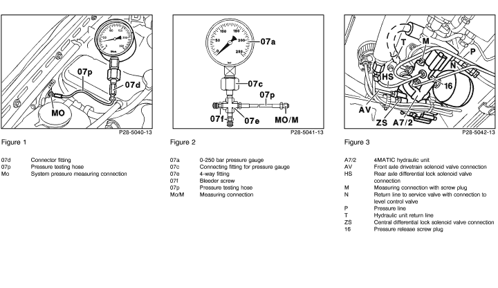
 250 bar gauge connected to service valve connection "MO". 250 bar gauge connected to service valve connection "MO".
(Figure 1, 2)
|
Engine: at idle
Service valve in operating position. |
25 - 36 bar |
Pressure < 25 bar: Oil supply pump, Service valve.
Pressure > 36 bar: hydraulic unit.

For testing vehicles with level control, refer to SMS Level control, Models 124, 201, Job No. 32-0530.
|
| 2.0 |
Pressure accumulator
Gas charge pressure
System pressure
|
Vehicles up to 04/91
Service valve in "TEST" position
 250 bar gauge connected to service valve connection "MO" 250 bar gauge connected to service valve connection "MO"
(Figure 1, 2)
Vehicles starting 05/91
Release accumulator pressure at screw plug (16, Fig. 3)
 250 bar gauge connected to service valve connection "M". 250 bar gauge connected to service valve connection "M".
(Figure 2, 3)
|
 Perform routinely only on vehicles with > 30,000 miles. Perform routinely only on vehicles with > 30,000 miles.
Engine: at idle
Service valve in operating position or switch (S7/3) in "FUNKTION" position. |
Rapid pressure increase to 10 - 22 bar, followed by slow pressure increase to 36 bar. |
Rapid pressure increase to 36 bar:
Pressure accumulator
Pressure < 25 bar: Oil supply pump
Pressure > 36 bar: Hydraulic unit.

For testing vehicles with level control, refer to SMS Level control, Models 124, 201, Job No. 32-0530.
|
 |
|


 Printable version


 Printable version