Listing of Test Steps
| 1 |
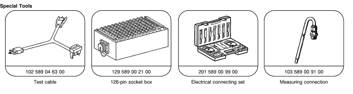
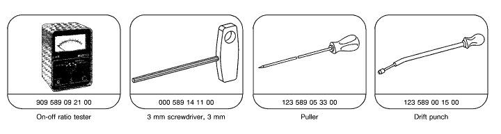
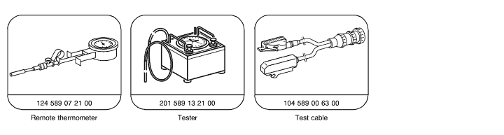
Test equipment |
connect/disconnect. |
| 2 |
CFI control module on-off ratio test (Ignition: ON ) |
perform. |
| 3 |
CFI control module on-off ratio test (Engine: closed throttle ) |
perform (wait until readout display oscillates). |
| 4 |
Diagnsotic trouble code read-out of CFI control module (Ignition: ON ) |
perform. |
| 5 |
Engine systems (MAS) control module (N16) diagnostic trouble code read-out (Ignition: ON ) |
perform. |
| 6 |
Ignition control module diagnostic trouble code read-out (at engine rpm) |
perform. |
| 7 |
Air filter |
remove and install. |
| 8.0 |
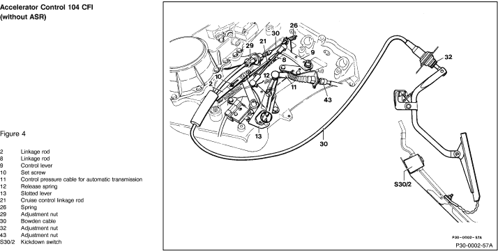
Linkage rods |
check throttle valve for free movement and condition. Lubricate bearings, slotted lever and ball sockets. |
| 8.1 |
Closed throttle (idle) contact |
check, adjust. |
| 8.2 |
Wide open throttle contact |
check using accelerator pedal, adjust. |
| 9 |
Control pressure cable |
check, adjust. |
| 10 |
Cruise control (without ASR) |
check, adjust. |
| 11 |
Engine coolant level |
check, correct. |
| 12 |
Engine oil level |
check, observe condition of oil. |
| 13 |
Voltage at ignition coils |
check (see Test and Adjustment Data, Section A). |
| 14 |
Ignition timing and vacuum advance |
check (see Test and Adjustment Data, Section A). |
| 15 |
Oscilloscope patterns |
evaluate (see section C). |
| 16 |
Engine oil temperature |
approximately 80 °C. |
| 17 |
Intake system |
check for leakage. |
| 18 |
Closed throttle (idle) speed |
check. |
| 19 |
Lambda control system |
test. |
| 20 |
Closed throttle under load |
check. |
 |
 |
 |
1) On engine 119 subtract 90° crankshaft from measured value.
Example: measured: 107° crankshaft, 107°-90°= 17° crankshaft timing |
Notes regarding on/off ratio check using on/off ratio tester
The operation of the Lambda control can be tested by checking the on/off ratio. In addition, any malfunctions that exist momentarily can be recognized. The tests distinguish between malfunctions that occur with the ignition ON or with the engine at idle .
The on/off ratio can be checked using the on/off ratio tester or engine analyzer. An on/off ratio of 50% indicates that all input signals are OK, but Lambda control is not functioning. A varying on/off ratio indicates that the Lambda control is functioning correctly. On/off ratios from 10% to 95% are each assigned a specific malfunction (see DTC memory, DM Engines, Volume 2, Section 2). After testing the on/off ratio, a diagnostic trouble code (DTC) readout using the impulse counter scan tool must always be performed.
Notes regarding diagnostic trouble code (DTC) readout using the Impulse counter scan tool

When diagnosing engine running complaints, or when the CHECK-ENGINE lamp is illuminated, the DTC memory should be read out and the DTC's noted before any repairs are attempted. This will ensure that the technician can differentiate between actual malfunctions and "simulated malfunctions," since testing done on a running engine will cause malfunctions to be stored that were caused by a simulation or a disconnected circuit.
When testing is completed, the DTC memory of the CFI and Ignition control modules and the Engine systems control module (MAS) must be cleared.
|
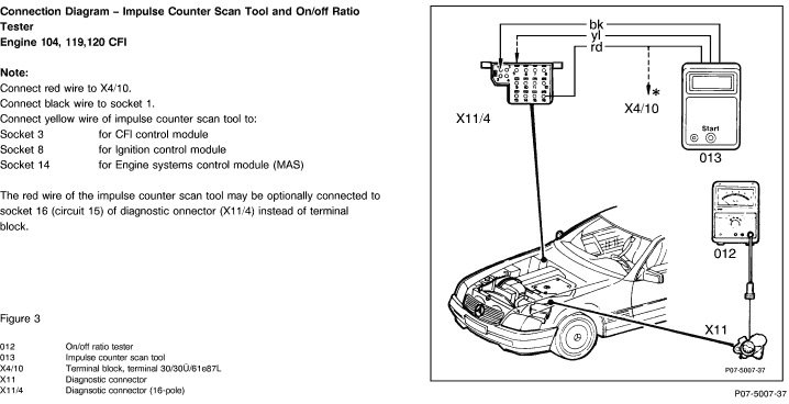
Notes regarding DTC readout using Impulse counter scan tool
1. Connect impulse counter scan tool according to diagram.
The LED "U-Batt" should come on. If not, check the following:
a) Voltage supply.
b) Impulse counter scan tool fuse.
2. DTC memory readout
a) Ignition: ON.
b) Push start button for 2-4 seconds.
c) Read and record DTC readout.
d) Push start button again.
e) Read and record DTC readout.
Repeats steps d) and e) until the first DTC readout reappears.
3. Clearing DTC memory
Note: The clearing process must occur within 20 seconds after the DTC readout.
a) Push start button 2-4 seconds (Impulse display appears).
b) After a waiting period of 3 seconds, push the start button for 6-8 seconds which will erase the previously displayed DTC.
c) Erase each DTC separately. |
Equipment
| Engine analyzer 1) |
Bear DACE (Model 40-960) with dual ignition adapter
Sun EMT-1019/Master 3 2)
Sun MCM-2110 2)
Sun MEA-1500MB 2) |
| Multimeter 1) |
Fluke Model 23, 83, 85, 87
Sun DMM-5 |
1) Available through the MBUSA Standard Equipment Program.
2) On engines with dual ignition system, only one cylinder bank can be measured at a time, using the present equipment. |
Note:
The Lambda control system test should not be performed on a very hot engine, for example, after a fast drive or after an output test on a dynamometer. |
| Test step/Test sequence |
Test condition |
Nominal value |
Possible cause/Remedy 1) |
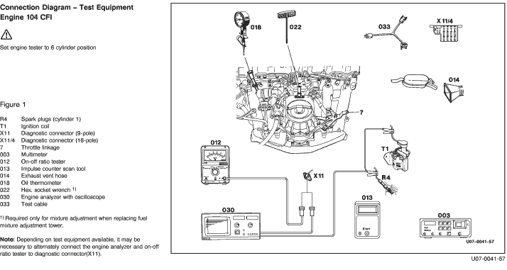
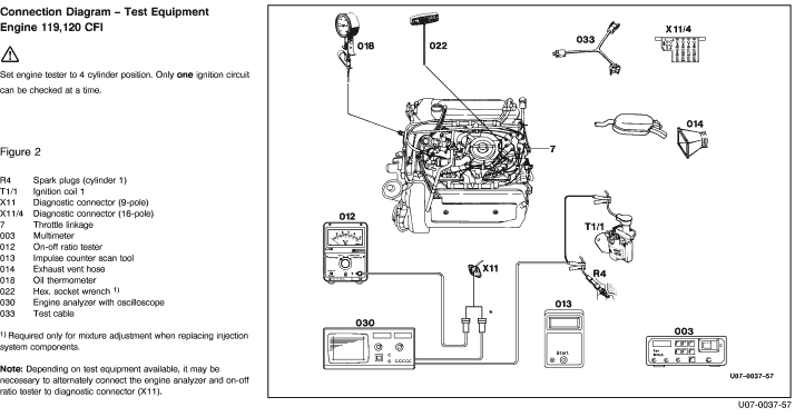
1
Connect test equipment according to diagram
|
Ignition: OFF |
- |
- |
2
CFI control module
on/off ratio readout
|
Ignition: ON
Coolant temperatue 80° C |
50% |
See DTC memory diagnosis
(DM Engines Vol. 2, Section 2)
|
3
CFI control module
on/off ratio readout
|
Engine: closed throttle (idle)
Coolant temperatue 80° C |
Readout oscillates |
See DTC memory diagnosis
(DM Engines Vol. 2, Section 2)
Adjust Lambda control  19 19 |
4
CFI control module
DTC readout |
Connect impulse counter scan tool:
yellow wire to socket 3 of diagnostic connector X11/4
Ignition: ON
|
DTC readout 1 |
See DTC memory diagnosis
(DM Engines Vol. 2, Section 2) |
5
Engine systems control module DTC readout |
Connect impulse counterscan tool:
yellow wire to socket 14 of diagnostic connector X11/4
Ignition: ON
|
DTC readout 1 |
See DTC memory diagnosis
(DM Engines Vol. 2, Section 2) |
6
Ignition control module
DTC readout |
Connect impulse counter scan tool:
yellow wire to socket 8 of diagnostic connector X11/4
Engine: Start
Vacuum hose to ignition control module connected. Hold engine at 3100-3600 rpm for 8 seconds.
Disconnect vacuum hose at idle, set parking brake, move selector lever from transmission range "P" to "D" and back to "P".
Hold engine at more than 5000 rpm for at least 2 seconds.
Reconnect vacuum hose at idle.
Raise engine to approx 2300 rpm, followed by brief opening to wide open throttle position (wide open throttle contacts must close).
Engine: closed throttle (idle)
Readout stored DTC's from memory. |
DTC readout 1 |
See DTC memory diagnosis
(DM Engines Vol. 2, Section 2)
|
7
Remove air cleaner
|
Ignition: OFF |
- |
- |
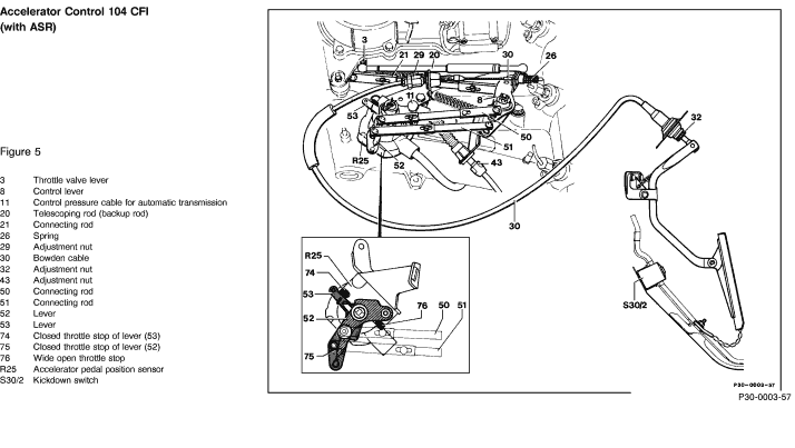
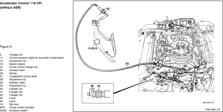
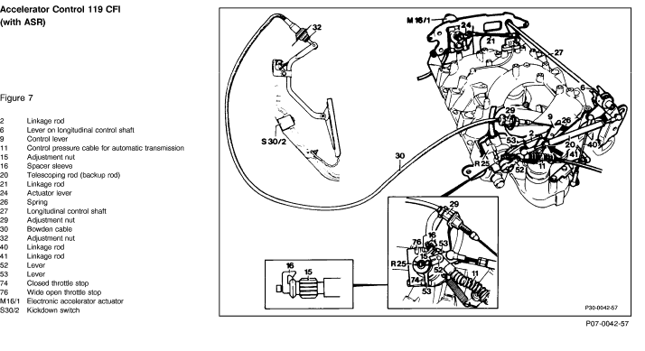
8.0
Check condition of linkage and throttle valve
|
Operate throttle linkage
without ASR: Ignition: OFF
with ASR: Ignition: ON |
Smooth operation, no binding should be evident. |
Lubricate all bearings and ball sockets |
8.1
Check closed throttle (idle) speed position |
Ignition: OFF
Accelerator pedal at closed throttle position |
Throttle valve lever must rest against closed throttle stop.
without ASR: Roller must contact slotted lever at closed throttle stop free of tension.
with ASR: Lever (53) must contact closed throttle stop.
|
Adjust throttle linkage
(SMS, Job No. 30-300) |
8.2
Check wide open (full) throttle position |
Ignition: ON, Engine OFF
Accelerator pedal at wide open throttle position
(not kickdown) |
without ASR: Throttle lever must stop approx. 0.5-1 mm away from the wide open throttle stop.
with ASR: Throttle lever must contact wide open throttle stop. |
Adjust throttle linkage
(SMS, Job No. 30-300) |
9
Check automatic transmission control pressure cable
|
Ignition: OFF
Accelerator pedal at closed throttle position |
Arrows must align (Fig. 4-7) |
Adjust control pressure cable
(SMS, Job No. 30-300) |
10
Check cruise control
(without ASR) |
Ignition: OFF
Accelerator pedal at closed throttle position |
Push actuator lever (Fig. 4-7) to closed throttle position, then pull approx. 1 mm away from closed throttle contact and adjust linkage rod (21) so that it can be attached free of tension.
|
Adjust throttle linkage
(SMS, Job No. 30-300) |
11
Engine coolant level
|
Ignition: OFF |
Marking: min - max |
Correct engine coolant level |
12
Engine oil level
|
Ignition: OFF |
Marking: min - max |
Correct oil level |
13
Check voltage at ignition coil |
Ignition: ON
Engine 104: Ignition coil T1
2  |
X11
 |
 5 |
11-14 V |
See checking ignition system, (DM Engines Vol. 2, Section 5) |
| |
4
|
X11
|
5 |
0 V |
|
| |
Engine 119: Ignition coil T1/1
2
|
X11
|
5 |
11-14 V |
|
| |
4
|
X11
|
5 |
0 V |
|
| |
Ignition coil T1/2
4 |
X11
|
5 |
11-14 V |
|
| |
4
|
X11
|
5 |
0 V |
|
1) Observe Preparation for Test, see  22 . 22 . |
| Test step/Test sequence |
Test condition |
Nominal value |
Possible cause/Remedy 1) |
14
Check ignition timing and vacuum advance |
Engine: Start
Check ignition timing at closed throttle.
Check ignition timing with and without vacuum at specified engine rpm.
|
See Test and adjustment data
(section A) |
See checking ignition system, (DM Engines Vol. 2, Section 5) |
15
Evaluate oscilloscope patterns |
Engine: closed throttle (idle)
Briefly accelerate to 3000 rpm |
Voltage difference between cylinders should be no more than 3kV.
Voltage increase with engine accelerated should be no more than 6 kV over idle value.
|
Evaluate with engine analyzer
(section C) |
16
Warm engine oil to operating temperature
|
Engine rpm: approx. 3000 rpm |
Engine oil temperature approx. 80 ° C |
- |
17
Check intake system for leakage |
Engine: closed throttle (idle)
Spray connections with carburetor cleaner.
Do not use conventional fuel for leak test (dangerous fumes). Note fire risk and do not spray on red hot parts or on ignition system.
|
- |
Repair leaks |
18
Check closed throttle (idle) rpm |
Engine: closed throttle (idle)
Transmission range "P", climate control system OFF, engine oil temperature approx. 80° C
|
See Test and adjustment data
(section A) |
Check closed throttle speed control
(DM Engines Vol. 2, Section 2) |
19
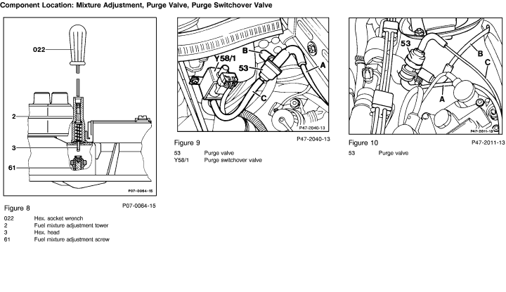
Adjust Lambda control system 2) |
Transmission range "P", climate control system OFF. Disconnect purge line to throttle valve housing at purge valve and plug. Reconnect line after measurment.
Engine oil temperature approx. 80° C.
Engine: closed throttle (idle)
|
See Test and adjustment data
(section A) |
If the specified value cannot be obtained, check electrical components with socket box tester
(DM Engines Vol. 2, Section 2) |
20
Check closed throttle under load |
Engine: closed throttle (idle)
Transmission range "D"
Switch on all electrical consumers,
Turn steering wheel to full lock. |
Engine must continue to idle within specified range. |
Check closed throttle speed control
(DM Engines Vol. 2, Section 2) |
1) Observe Preparation for Test, see 22 .
2) The fuel mixture adjustment screw is secured against unauthorized adjustment by means of a steel ball in the adjustment tower. After fuel mixture adjustment at the factory, the ball is installed in the adjustment tower using a special tool and must not be removed.
The fuel mixture may only be corrected when replacing a fuel injection system component or when performing an engine repair. To do so, the fuel mixture adjustment tower must be replaced. |
|


 Printable version