STI Home
Diagnostic Manual, Engines, Volume 1

 Printable version
LOCATION:    B.2 Test and Adjustment Jobs    >   31 Idle Test, Adjustment


B 2 Idle Test, Adjustment

Listing of Test Steps

1 Test equipment connect/disconnect.
2.0 Throttle control check throttle operation and condition.
2.1 Closed throttle stop check.
3 Ignition timing and vacuum advance check (see Test and Adjustment Data, Section A).
4 Engine oil temperature approx. 80 °C.
5 Closed throttle rpm check
6 Lambda control check
7 Closed throttle under load check in transmission range D with all electrical consumers on.

Connection chart for test equipment without diagnostic adapter for two circuit ignition systems

Test equipment
version
Cylinder no. setting on test equipment Type of measurement Circuit on Diagnostic socket
Trigger clamp on ignition cable kV-Clamp on ignition cable
ignition circuit
SUN
MEA-1500MB
4


RPM/
dwell angle
of Ignition circuit


T1/1


Timing
of Ignition circuit

T1/1
Cylinder 1
T1/1
Timing
of Ignition circuit

T1/2
Cylinder 2 1)
T1/2
Oscilloscope
primary/secondary
and voltage at
terminal 15/1 of Ignition coil

T1/1


Cylinder 1
Firing order on oscilloscope 1-4-6-7

T1/1
Firing order on oscilloscope 1-4-6-7

Oscilloscope
primary/secondary
and voltage at
terminal 15/1 of Ignition coil

-


Cylinder 5
Firing order on oscilloscope 5-8-3-2
T1/2
Firing order on oscilloscope 5-8-3-2
1) Subtract 90 °CKA from measured value.,
Example: measured: 107 °crankshaft, 107-90= 17 °crankshaft timing

Equipment

Engine analyzer 1) Bear DACE (Model 40-960)
Sun EMT-1019/Master 3
Sun MCM-2110
Sun MEA-1500MB
Digital multimeter 1) Fluke Models 23, 83, 85, 87
1) Available through the MBUSA Standard Equipment Program.

Note:
The Lambda control system test should not be performed on a very hot engine, for example, after a fast drive or after an output test on a dynamometer.

1
Connect test equipment according to diagram
Ignition: OFF - -
2
Check condition of linkage and throttle valve
Operate throttle linkage
without ASR: Ignition: OFF
with ASR: Ignition: ON
Smooth operation, no binding should be evident. Lubricate all bearings and ball sockets
2.1
Check idle speed position
Engine: Idle Throttle valve lever must rest against idle stop. Adjust throttle linkage
(SMS Job No. 30-300)
3
Check ignition timing and vacuum advance
Engine: Start
Check ignition timing at idle
Check ignition timing with and without vacuum at specified engine rpm.
Test and adjustment data (section A) DM, Engines, Volume 2, Section 5.1
4
Warm engine oil to operating temperature 80° C
Engine rpm: approx. 3000 rpm Engine oil temperature approx. 80 °C -
5
Check idle rpm
Engine: idle
Selector lever in P position,
climate control system OFF,
engine oil temperature approx. 80° C
Test and adjustment data (section A) DM, Engines, Volume 2, Section 2.1
6
Check Lambda control system 1)
Selector lever in P position,
climate control system OFF,
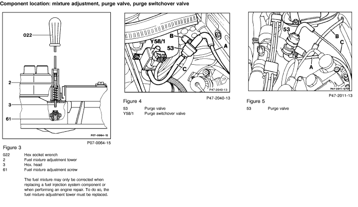
Disconnect purge line to throttle valve housing at purge valve and plug. Reconnect line after measurement.
Engine oil temperature approx. 80° C.
Engine: idle
Test and adjustment data (section A) DM, Engines, Volume 2, Section 2.1

7
Check idle under load
Engine: idle
Transmission range D.
Switch on all electrical consumers,
Turn steering wheel to full lock.
Engine must continue to idle within specified range. DM, Engines, Volume 2, Section 2.1
1) The fuel mixture adjustment screw is secured against unauthorized adjustment by means of a steel ball in the adjustment tower. After fuel mixture adjustment in the factory, the ball is installed in the adjustment tower using a special tool and must not be removed.

The fuel mixture may only be corrected when replacing a fuel injection system component or when performing an engine repair. To do so, the fuel mixture adjustment tower must be replaced.