Diagnostic Manual, Engines, Volume 2
Electrical Test Program - Preparation for Test
Preliminary work: Diagnosis - Malfunction Memory  11 11 |
Preparation for Test
1. Ignition: OFF
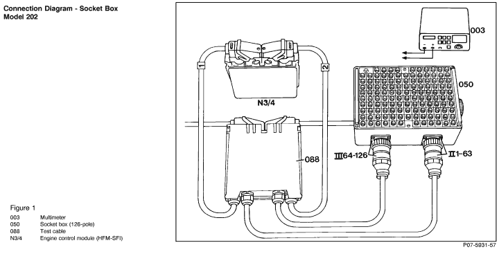
2. Connect test cable with socket box to engine control module (N3/4) according to connection diagram.
Electrical wiring diagrams, see Electrical Troubleshooting Manual.
 If installing an engine control module from another vehicle (only possible on vehicles without drive authoriation system (DAS) up to the end of model year 1995), the control module's memory must be erased and the control module must be reactivated, see If installing an engine control module from another vehicle (only possible on vehicles without drive authoriation system (DAS) up to the end of model year 1995), the control module's memory must be erased and the control module must be reactivated, see  11 /5. 11 /5.
Note regarding "Test Connection" column:
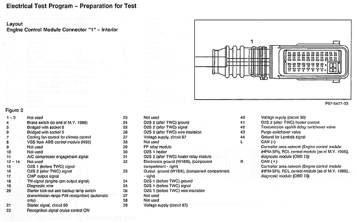
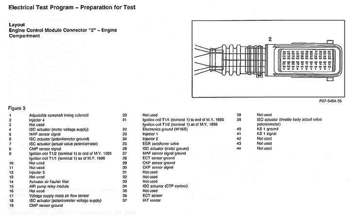
The numbers indicated in parentheses, for example,  1.0 (1.23) signify: 1.0 (1.23) signify:
1= Connector 1 on wiring diagram,
23= Socket 23 on wiring diagram. |
Conventional tools, test equipment
| Description |
Brand, model, etc. |
| Multimeter 1) |
Fluke models 23, 83, 85, 87 |
| Engine analyzer 1) |
Bear DACE (Model 40-960)
Hermann Model D960S
Sun MEA-1500MB |
| 1) Available through the MBUSA Standard Equipment Program. |
 WARNING! WARNING!
Conductive parts of the ignition system are under high voltage. Never touch conductive parts when the ignition is switched on, when the engine is being "turned over" manually or with the starter, or when the engine is running.
Persons with heart pacemakers should never perform work on the ignition system.
Electronic ignition systems operate in a dangerously high voltage range on the low voltage side (primary circuit) as well as on the high voltage side (secondary circuit). Due to the high voltages in electronic ignition systems contact with parts or terminals under power can be dangerous.
Always switch off the ignition when working on the ignition system, e.g.:
 Replacing ignition system components Replacing ignition system components
 Connecting engine test instruments Connecting engine test instruments
 Connecting removed assemblies for testing on test benches Connecting removed assemblies for testing on test benches
If it is necessary to switch on the ignition for work on the ignition system, observe safety precautions, dangerously high voltage is present in the entire ignition system.
Ensure that the engine and ignition are turned off when connecting/ disconnecting equipment such as voltage signal pick-up on respective ignition cables and trigger pick-up on cylinder 1.
See Service Microfiche System (SMS), Repair Instructions, group 15 for further safety precautions. |
| |
 |
Notes for avoiding damage to ignition systems during testing:
 To avoid damage to the control module, disconnect and connect control module connectors with the ignition switched off . To avoid damage to the control module, disconnect and connect control module connectors with the ignition switched off .
 Do not connect a test lamp to circuit 1 or 15 of ignition coil. Do not connect a test lamp to circuit 1 or 15 of ignition coil.
 Terminal 1 of the ignition coils must not be short-circuited to ground, e.g. anti-theft protection. Terminal 1 of the ignition coils must not be short-circuited to ground, e.g. anti-theft protection.
 Install only original ignition system components. Install only original ignition system components.
 Do not operate the ignition system at cranking speed unless the ignition wires are fully connected. Do not operate the ignition system at cranking speed unless the ignition wires are fully connected.
 The following ignition tests should not be performed with engine cranking or with the engine running: holding secondary coil wire at a distance to ground, disconnecting a spark plug connector, or pulling secondary coil wire out of the ignition coil(s). The following ignition tests should not be performed with engine cranking or with the engine running: holding secondary coil wire at a distance to ground, disconnecting a spark plug connector, or pulling secondary coil wire out of the ignition coil(s).
 Each high-voltage circuit must have a load of at least 2 k Each high-voltage circuit must have a load of at least 2 k  (plug connector). (plug connector).
 On the separate ignition coil tests, the ignition coil must not be loaded above 28 kV to avoid damaging the ignition coil. On the separate ignition coil tests, the ignition coil must not be loaded above 28 kV to avoid damaging the ignition coil.
 If engine cuts out when using engine analyzer during cylinder balance test, do not perform further testing with that type of engine analyzer. If engine cuts out when using engine analyzer during cylinder balance test, do not perform further testing with that type of engine analyzer.
 If it is necessary to check the ignition spark following a breakdown, check with spark plug connected to one of the secondary ignition wires. Ensure that the spark plug is well grounded. If it is necessary to check the ignition spark following a breakdown, check with spark plug connected to one of the secondary ignition wires. Ensure that the spark plug is well grounded.
 When working at cranking speed, e.g. checking compression, switch off ignition and: When working at cranking speed, e.g. checking compression, switch off ignition and:
On engine with HFM-SFI/ME-SFI fuel injection and ignition system, disconnect connector "2" on control module.
|
 |
 |
 |
|


 Printable version


 Printable version