Diagnostic Manual, Engines, Volume 2
How To Use
The Diagnostic Manual "Engines" is divided into 4 volumes, whereby sections in Volume 1 are in alphabetical order and sections in Volume 2 through 4 are in numerical order.
Contents Volume 1: Test and Adjustment Data, Test and Adjustment Jobs, Diagnostic Equipment and Diagnostic Methods.
Contents Volume 2, 3 or 4: Connection and Use of Test Equipment, Test Procedures for individual systems such as: Continuous fuel injection system (CFI), LH sequential multiport fuel injection (LH-SFI), HFM sequential multiport fuel injection/ignition system (HFM-SFI), ME sequential multiport fuel injection/ignition system (ME-SFI), Distributor ignition (DI) and Electronic Accelerator (EA)
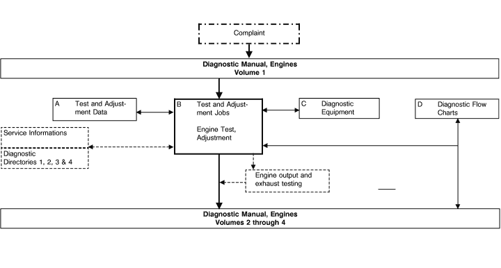
In case of engine complaints, begin with the procedure for "Engine Test, Adjustment". If malfunctions occur after performing repair or maintenance work (e.g. Testing On-Off Ratio), begin with the test procedures in Volumes 2 through 4.
When diagnosing complaints, always refer to the Diagnostic Directory Microfiche or Service Informations first for possible coverage of the respective topic and its solution.
Certain test procedures may require the completion of preliminary work first. A reference to Preliminary Work required, if any, is made at the beginning of the test.
Part numbers are listed only to identify and to differentiate individual versions with respect to test values in a test procedure. Always refer to the applicable Parts Microfiche when selecting part numbers for a parts order.
Diagnostic test equipment and their measurement capabilities are described in Volume 1, Section C. The measurement results attained are explained and malfunctions are illustrated with examples. The use of this equipment allows more in-depth testing when diagnosing engine running complaints. Many of these tests can be carried out using standard test and adjustment equipment.
In addition, oscilloscope patterns are provided to assist in diagnosis.
Examples of diagnostic methods illustrated in the form of flow charts are contained in volume 1, section D.
Expanded procedures necessary for testing individual systems are contained in Volumes 2 through 4.
The individual test steps (e.g. engine coolant temperature sensor, intake air temperature sensor, etc.) are combined into a Test Program.
If an complaint is verified during engine diagnosis in Volume 1, and there is a reference to an individual test step, perform only that test step and not the entire test program.
The flow chart on the following page depicts the use of the Diagnostic Manual, Volumes 1, 2, 3 and 4. |
 |
 |
|


