Diagnostic Manual, Climate Control, Volume 1
Diagnosis - Diagnostic Trouble Code (DTC) Memory

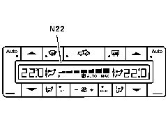
 The A/C pushbutton control module (N22) has DTC memory and data output. The diagnostic trouble codes and data are displayed via the temperature display window. The stored DTC's will remain in memory even with the vehicle battery disconnected. The A/C pushbutton control module (N22) has DTC memory and data output. The diagnostic trouble codes and data are displayed via the temperature display window. The stored DTC's will remain in memory even with the vehicle battery disconnected.
 The DTC memory differentiates between current and intermittent faults. The DTC memory differentiates between current and intermittent faults.
 Numerous DTC's can also be read with the Hand-Held Tester (HHT). Numerous DTC's can also be read with the Hand-Held Tester (HHT). |
|
 |
| |
|
P83.40-2110-01 |
Preparations for DTC Readout
1. Review  11, 11,  12 , 12 ,  13 , 13 ,  14 , 14 ,  15 , 15 ,  21 , 21 ,  22 , 22 ,  31 , 31 ,  32 , 32 ,
 41 , 41 ,
2. Ignition: ON
3. Temperature selector: left:     ; right: ; right:    
4. Ignition: OFF
5. Ignition: ON
6. Within 20 seconds press  and and  simultaneously for more than 5 seconds. simultaneously for more than 5 seconds.
7. The LED in  flashes and the display shows flashes and the display shows      . .
8. Press  repeatedly until all DTC's are displayed. Record each DTC as it is displayed. repeatedly until all DTC's are displayed. Record each DTC as it is displayed.
9. Each fault (short circuit, open circuit) is assigned a DTC. Thus in the left display: "   " appears, and the right display indicates the DTC. " appears, and the right display indicates the DTC.
The current faults (refer to table) are displayed first, next, the intermittant failures (e.g. 45 °5) are displayed in the display window next to the  symbol. By pressing the right symbol. By pressing the right  the next DTC is displayed. the next DTC is displayed.
10. To erase: Can only be performed after all faults have been readout.
Press left  and right and right  buttons simultaneously for buttons simultaneously for
more than 2 seconds and the display shows:
left: "d" and right: "FF".
To cancel erase: By pressing the left  button, the current faults will appear again. button, the current faults will appear again.
11. Select a base temperature setting.
12. Turn ignition OFF, to end test.

Due to instrument cluster (IC) series interface, DTC's may be stored in IC memory, therefore readout and erase DTC's from IC memory.
|
 |
Diagnostic trouble code (DTC)
N22  |
Possible cause |
Test step/Remedy 1) |
| - - |
No malfunction in system |
- |
        |
In-car temperature sensor (B10/4)

Model 208.465: With the soft top down, the power soft top control module (N52) will override B10/4 and in this case, the DTC      will not be stored in memory. will not be stored in memory. |
 23 23  4.0 4.0 |
        |
Outside temperature indicator temperature sensor (B14) |
 23 23  11.0 11.0 |
        |
Heater core temperature sensor (B10/1) (left) |
 23 23  7.0 7.0 |
        |
Heater core temperature sensor (B10/1) (right) |
 23 23  7.0 7.0 |
        |
Evaporator temperature sensor (B10/6) |
 23 23  5.0 5.0 |
        |
ECT sensor (B11/4 ) |
 23 23  11.0 11.0 |
        |
Refrigerant pressure sensor (B12) |
 23 23  9.0 9.0 |
        |
Refrigerant temperature sensor (B12/1) |
 23 23  6.0 6.0 |
        |
Refrigerant fill level |
 23 23  9.0 , 6.0 9.0 , 6.0 |
        |
Coolant circulation pump (M13) |
 23 23  15.0 15.0 |
        |
Left-side water valve (Y21y1) |
 23 23  16.0 16.0 |
        |
Right-side water valve (Y21y2) |
 23 23  16.0 16.0 |
        |
Electromagnetic clutch (A9k1) |
 23 23  18.0 18.0 |
        |
Idle speed increase |
- |
        |
AIR control module (N65/1) |
 23 23  12.0 12.0 |
        |
Serial interface K1 |
 23 23  11.0 , 11.0 ,
 21 (CAN) 21 (CAN) |
        |
Switchover flap (Y11) |
 23 23  19.0 19.0 |
        |
Non-USA Test Step |
- |
        |
Serial interface K2 |
 23 23  12.0 , 12.0 ,
 21 (CAN) 21 (CAN) |
1) Observe Preparation for Test, see  22 . 22 . |
|


 Printable version


 Printable version