Diagnostic Manual, Climate Control, Volume 1
Pneumatic Test Program - Test
Preparation for Test
A. Pneumatic test: vacuum distributor block, vacuum reservoir, switchover valve block (Y11)
1. Review  11 , 11 ,  12 , 12 ,  13 , 13 ,  14 , 14 ,  15 , 15 ,  20 , 20 ,  21 , 21 ,  22 , 22 ,
 31 , 31 ,  32 , 32 ,  41 , 41 ,  42 42
2. Disconnect all vacuum lines at vacuum distributor block (36).
3. Check gray vacuum line to intake manifold for leaks.

Permissible leakage of the elements with vacuum lines at 400 mbar vacuum per minute is  30 mbar. 30 mbar.
|
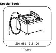
Test equipment; See MBUSA Standard Service Equipment Program
| Description |
Brand, model, etc. |
| Connector |
129 805 04 44 |
| A. Vacuum Distributor Block, Vacuum Reservoir, Valve Block (Y11) Test |
 |
Test scope |
Test connection |
Test condition |
Nominal value |
Possible cause/Remedy |
| 1.0 |
Entire vacuum distributor block |
Connection "P" on vacuum tester. |
Evacuate system with
300 mbar vacuum. |
 30 mbar 30 mbar
pressure
increase in
1 minute.
|
Vacuum distributor block,
 1.1 1.1 |
| 1.1 |
Vacuum distributor block,
check valve "a" |
Connection "1" on vacuum tester. |
Evacuate system with
300 mbar vacuum. |
 30 mbar 30 mbar
pressure
increase in
1 minute.
|
Vacuum distributor block,
 1.2 1.2 |
| 1.2 |
Vacuum distributor block,
check valve "b" |
Connection "4" on vacuum tester. |
Evacuate system with
300 mbar vacuum. |
 30 mbar 30 mbar
pressure
increase in
1 minute.
|
Vacuum distributor block. |
| 2.0 |
Vacuum reservoir with
vacuum line |
Red/gray vacuum line (connection 3) on vacuum tester. |
Evacuate system with
300 mbar vacuum. |
 30 mbar 30 mbar
pressure
increase in
1 minute.
|
Vacuum lines,
Vacuum reservoir. |
| 3.0 |
Switchover valve
block (Y11) |
Ignition: OFF
medium green line (connection 2) on vacuum tester. |
Evacuate system with
300 mbar vacuum. |
 30 mbar 30 mbar
pressure
increase in
1 minute.
|
Vacuum lines,
Y11. |
Preparation for Test
B. Vacuum system
1. Ignition: ON
2. Press  and and  > 5 secs. > 5 secs.
3. Medium green line (connection "5") on vacuum tester.
4.  (fan) speed will increase. (fan) speed will increase. |
|
 |
| |
|
|
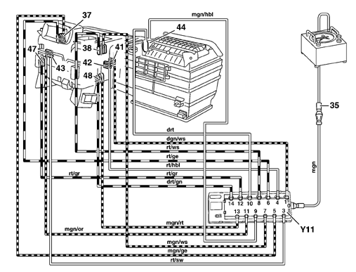
B. Vacuum system test A
1. Left display  : vacuum actuators 37, 38, 47 and 48 (medium green and red vacuum lines) with vacuum applied. : vacuum actuators 37, 38, 47 and 48 (medium green and red vacuum lines) with vacuum applied.
2. Left display  and and  : vacuum actuator 41 (medium green vacuum line) with vacuum applied. : vacuum actuator 41 (medium green vacuum line) with vacuum applied.
3. If vacuum on guage drops: remove lines from valve block (Y11) and then individually test lines and vacuum actuators.
4. Replace any defective vacuum actuator(s) or pneumatic line(s).
|
|
 |
| |
|
|
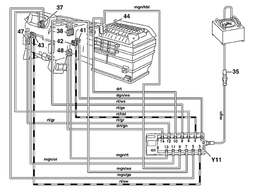
B. Vacuum system test B
1. Left display  and and  : vacuum actuators 42 and 43 (red vacuum line). In addition vacuum actuators 37 and 38 (see B. vacuum diagram 1)on following page. : vacuum actuators 42 and 43 (red vacuum line). In addition vacuum actuators 37 and 38 (see B. vacuum diagram 1)on following page.
2. If vacuum on guage drops: remove lines from valve block (Y11) and then individually test lines and vacuum actuators.
3. Replace any defective vacuum actuator(s) or pneumatic line(s).
Vacuum diagram 2
Vacuum diagram 2 |
|
 |
| |
|
|
B. Vacuum diagram 1
|
|
 |
| |
|
|
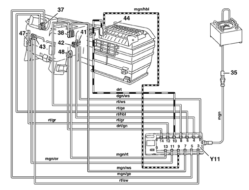
B. Vacuum system test C
1. Left display   and and   : vacuum actuators 44 (dark red and medium green vacuum lines). In addition vacuum actuators 42 and 43 see (vacuum diagram 2) on following page. : vacuum actuators 44 (dark red and medium green vacuum lines). In addition vacuum actuators 42 and 43 see (vacuum diagram 2) on following page.
2. If vacuum on guage drops: remove lines from valve block (Y11) and then individually test lines and vacuum actuators.
3. Replace any defective vacuum actuator(s) or pneumatic line(s).
|
|
 |
| |
|
|
B. Vacuum diagram 2
|
|
 |
| |
|
|
|


 Printable version


 Printable version