Diagnostic Manual, Climate Control, Volume 1
Refrigerant System Test Program - Preparation for Test
1. Prior to hooking up and using test equipment: review section 0
2. Review  11, 11,  12, 12,  13, 13,  14, 14,  15, 15,  20, 20,  21, 21,  22, 22,  31, 31,  32, 32,  41, 41,  42 42
3. Review special tools, see below.
4. Perform complete Function Test, see:  11 /1 11 /1
5. Refrigerant fill level must be correct (refer to fill level chart).
6. Connect gauges to low and high pressure test connections.
7. Engine at operating temperature.
8. Center and side air outlets open.
9. Test duration > 3 minutes.
10. Press  button (should illuminate). button (should illuminate).
11. Vehicle should not be parked in the sun before or during the test.
12. Open doors and windows. |
Test equipment; See MBUSA Standard Service Equipment Program
| Description |
Brand, model, etc. |
| Multimeter 1) |
Fluke models 23, 83, 85, 87 with thermocouple
Module 80TK |
| Manifold gauge set (for R134a only) |
Local purchase |
| R134a Recovery/Recycling/Recharging Service Equipment |
Local purchase |
| 1) Available through the MBUSA Standard Equipment Program. |
 |
| Test condition |
Low pressure (bar, B) |
High pressure (bar, C) |
Center air outlet temperature (A) |
Auxiliary fan |
Damaged component (cause of failure) |
Remedy |
Blower at highest setting
Display     , ,
Center and side air outlets open,
Engine speed 3000 rpm. |
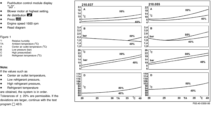
1 bar higher as in diagram  42 /2 42 /2 |
As in diagram  42/2 42/2 |
> as in diagram  42 /2 42 /2 |
Possibly for a short period |
A/C compressor
(Insufficient delivery capacity) |
Replace A/C compressor
(AR83.55-P-5300F)
|
Blower at middle output setting.
Press 
Engine speed 1500 rpm |
> as in diagram
 42 /2 42 /2 |
17 - 22 bar |
Starting at
5 - 8 oC
increasing depending on ambient temp. |
I or II stage depending on pressure and temperature |
Expansion valve
(continuously open) |
Replace expansion valve
(AR83.30-P-5520E) |
Display "HI",
Press 
Engine speed 1500 rpm |
Pulsates |
< as in diagram
 42 /2 42 /2 |
Heated air |
Only via engine coolant temperature |
Expansion valve
(continuously closed)
Low pressure lines
(insufficient flow) |
Replace expansion valve
(AR83.30-P-5520E)
|
Display "HI",
Blower stage 3,
Press 
Engine speed 1500 rpm |
< as in diagram |
significantly > as in diagram pressure A |
as in diagram
 42 /2 42 /2 |
On (runs). |
High pressure line blocked; up to refrigerant pressure sensor (B12) |
High pressure line(s) |
|


 Printable version


 Printable version