Diagnostic Manual, Climate Control, Volume 1
Diagnosis - Diagnostic Trouble Code Memory

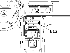
 The A/C pushbutton control module (N22) has DTC memory and data output. The diagnostic trouble codes and data are displayed via the display window. The stored DTC's will remain in memory even with the vehicle battery disconnected. The A/C pushbutton control module (N22) has DTC memory and data output. The diagnostic trouble codes and data are displayed via the display window. The stored DTC's will remain in memory even with the vehicle battery disconnected.
 The DTC memory differentiates between current and intermittent faults. The DTC memory differentiates between current and intermittent faults.
 All DTC's can also be read with the Hand-Held Tester (HHT). All DTC's can also be read with the Hand-Held Tester (HHT).
 Connect HHT as indicted in section 0. Connect HHT as indicted in section 0. |
|
 |
| |
|
P83.40-0304-01 |
Preparation for Test
1. Ignition: ON
2. Left display "   ", right display " ", right display "   ". ".
3. Within 20 secs., press  and and  simultaneously for > 5 secs. simultaneously for > 5 secs.
4. The LED in  flashes and the display window reads flashes and the display window reads    . .
5. Press right  > 1 sec. If there are no DTC's: > 1 sec. If there are no DTC's:  is displayed in the left side of the display window and is displayed in the left side of the display window and   is displayed in the right side. is displayed in the right side.
If DTC's are stored in memory:    is displayed in the left side of the display window and the DTC (e.g. is displayed in the left side of the display window and the DTC (e.g.    ) is displayed in the right side (record each DTC as it is displayed). ) is displayed in the right side (record each DTC as it is displayed).
6. Each malfunction (short circuit, open circuit, etc.) has a specific DTC (the DTC is displayed in the right side of the display window,    is displayed in the left side). is displayed in the left side).
By pressing  the next DTC is displayed (see table). the next DTC is displayed (see table).
7. To Erase: (all DTC's must first be read out) press right and left  > 2 secs., > 2 secs.,  will be displayed in the left side of the display window and will be displayed in the left side of the display window and   in the right side. in the right side.
To cancel erase: press right  , the current faults will appear again (compare to DTC readout recorded earlier). , the current faults will appear again (compare to DTC readout recorded earlier).
Delete DTC's as often as necesarry until  is displayed in the left side of the display window and is displayed in the left side of the display window and   is displayed in the right side. is displayed in the right side.
8. Set temperature selector to normal setting.
9. Ignition OFF to end test.
|
Display code in
N22 window |
 |
Possible cause |
Test step/Remedy 1) |
  |
- |
No malfunction in system |
- |
   |
     |
CAN communication with rear A/C |
Wiring |
   |
     |
In-car temperature sensor (B10/4) |
 23 23  4.0 4.0 |
   |
     |
Outside temperature indicator temperature sensor (B14) |
 23 23  10.0 10.0 |
   |
     |
Left heater core temperature sensor (B10/2) |
 23 23  7.0 7.0 |
   |
     |
Right heater core temperature sensor (B10/3) |
 23 23  8.0 8.0 |
   |
     |
Evaporator temperature sensor (B10/6) |
 23 23  5.0 5.0 |
   |
     |
ECT sensor (DFI, IFI) (B11/4) |
 23 23  9.0 9.0 |
   |
     |
Refrigerant pressure sensor (B12) |
 23 23  11.0 11.0 |
   |
     |
Refrigerant temperature sensor (B12/1) |
 23 23  6.0 6.0 |
   |
     |
Sun sensor (B32) |
 23 23  12.0 12.0 |
   |
     |
Emissions sensor (B31) |
 23 23  14.0 14.0 |
   |
     |
Refrigerant fill |
 23 23  6.0 , 11.0 6.0 , 11.0 |
   |
     |
Coolant circulation pump (A31m1) |
 23 23  17.0 17.0 |
      |
     |
Left-side water valve (Y21y1) |
 23 23  18.0 18.0 |
      |
     |
Right-side water valve (Y21y2) |
 23 23  18.0 18.0 |
      |
     |
Electromagnetic clutch (A9k1) |
 23 23  21.0 21.0 |
      |
     |
Idle speed increase |
- |
      |
     |
AIR control module (N65/1) |
 23 23  15.0 15.0 |
      |
     |
Serial interface (K1) to instrument cluster (A1) |
 23 23  30.0 30.0 |
      |
     |
Switchover valve block (Y11) |
 23 23  20.0 20.0 |
      |
     |
Activated charcoal filter actuator(A32m2) open |
 23 23  22.0 22.0 |
      |
     |
Activated charcoal filter actuator (A32m2) closed |
 23 23  22.0 22.0 |
      |
     |
Auxiliary heater-NON-USA (continue to next test step) |
- |
      |
     |
Serial interface (K2) to instrument cluster (A1) |
 23 23  31.0 31.0 |
      |
     |
LED - Center air outlet "Warm" |
 23 23  24.0 24.0 |
      |
     |
LED - Center air outlet "Cold" |
 24 24  25.0 25.0 |
      |
     |
Wide open throttle (WOT) position (diesel engines) |
- |
1) Observe Preparation for Test, see  22 . 22 . |
|


 Printable version


 Printable version