Diagnostic Manual, Climate Control, Volume 1
Electrical Test Program - Preparation for Test
1. Review  11 , 12 , 13 , 14 , 15 , 21 , 22 , 23 , 31 , 11 , 12 , 13 , 14 , 15 , 21 , 22 , 23 , 31 ,
32 , 41
2. Remove A/C pushbutton control module (N22).

Upon completion of test, erase DTC memory from A/C pushbutton control module (see 15 ).
Electrical Test Program: Rear A/C only, starts on 23/11
Electrical wiring diagrams:
Electrical Troubleshooting Manual, Model 140
|
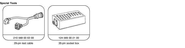
Test equipment; See MBUSA Standard Service Equipment Program
| Description |
Brand, model, etc. |
| Multimeter 1) |
Fluke models 23, 77 III, 83, 85, 87 |
| 1) Available through the MBUSA Standard Equipment Program. |
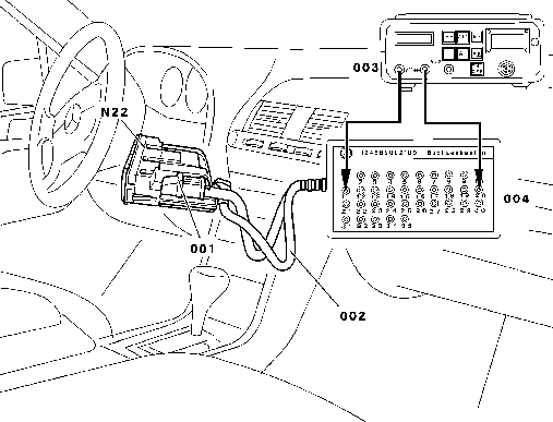
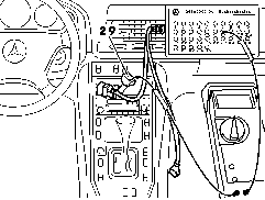
Electrical Components in Passenger Compartment
Front A/C
Figure 1
001 Right connector, A/C pushbutton
control module
002 Test cable
003 Multimeter
004 Socket box
N22 A/C pushbutton control module |
|
 |
| |
|
P83.40-0311-06 |
Connection diagram for testing the electrical resistance of the following sensors:
 In-car temperature sensor with aspirator In-car temperature sensor with aspirator
Evaporator temperature sensor
Refrigerant temperature sensor
Left heater core temperature sensor
Right heater core temperature sensor
ECT sensor
Outside temperature sensor
Figure 2
|
|
 |
| |
|
P83.40-0307-01 |
Rear A/C
Figure 3
N22/3 Rear A/C pushbutton control module
001 Right connector, A/C pushbutton
control module
002 Test cable
003 Multimeter
004 Socket box
|
|
 |
| |
|
P83.50-2018-05 |
|


 Printable version