Diagnostic Manual, Engines, Volume 3
Electrical Test Program - Test
Test step
|
DTC |
Scope of test
|
Test connection
|
Test condition
|
Nominal value
|
Possible cause/remedy
|
| 1.0 |
|
Diagnostic module (N59)
Voltage supply
Circuit 30 |
25  (1.25) (1.25) |
N59


|
 5
(1.5) |
Ignition: ON |
11 - 14 V |
 1.1 - 1.3. 1.1 - 1.3.
|
| 1.1 |
|
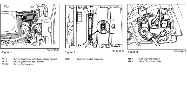
Ground, output ground, electronics (W15)
(right footwell)
|
N59

25  1.25) 1.25) |
|
X11/4
 2 |
Ignition: ON |
11 - 14 V |
Ground wire at W15.
|
| 1.2 |
|
Base module (N16/1)
Voltage supply
Circuit 30
|
28 
(1.28) |
N16/1


|
 1
(3.1) |
Connect socket box to N16/1.
Ignition: ON |
11 - 14 V |
Wire to terminal block (X4/10). |
| 1.3 |
9 |

Diagnostic trouble code from base module (N16/1)
Voltage supply from N16/1 to diagnostic module (N59)
Circuit 30
|
29 
(1.29) |
N16/1


|
 12
(1.12) |
Ignition: ON |
11 - 14 V |
N16/1. |
| 2.0 |
|
Diagnostic module (N59)
Voltage supply
Circuit 87L
|
25 
(1.25) |
N59


|
 26
(1.26) |
Ignition: ON |
11 - 14 V |
 2.1 - 2.2. 2.1 - 2.2. |
| 2.1 |
|
Base module (N16/1)
Voltage supply
Circuit 15, unfused |
28 
(1.28) |
N16/1


|
 34
(1.34) |
Connect socket box to N16/1.
Ignition: ON
Ignition: OFF |
11 - 14 V
<1 V |
Open circuit,
Ignition/starter switch (S2/1).
Open circuit,
S2/1.
|
| 2.2 |
1 0 |

Diagnostic trouble code from base module (N16/1)
Voltage supply (fused) for right LH-SFI control module (N3/3)
|
28 
(1.28) |
N16/1


|
 7
(1.7) |
Ignition: ON
Ignition: OFF |
11 - 14 V
<1 V |
Fuse (F2) at N16/1,
N16/1.
|
| 3.0 |
|
Control of "CHECK ENGINE" MIL
|
28 
(1.28) |
N59


|
 26
(1.26) |
Ignition: ON
|
11 - 14 V |
N59. |
| 4.0 |
|
Control of diagnostic wire |
25 
(1.25) |
N59


|
 27
(1.27) |
Ignition: ON
|
11 - 14 V
|
Open circuit,
N59. |
| 5.0 |
|
Control of DM test connector pushbutton (X11/21s1) |
33 
(2.33) |
N59


|
'
 26
(1.26) |
Ignition: ON
Press pushbutton (X11/21s1).
|
11 - 14 V |
Open circuit,
DM test connector (X11/21),
N59.
|
| 6.0 |
|
CAN data bus |
L  |
N59

|
 H |
Ignition: OFF
Pull out contact module or diagnostic module. Test with ohmmeter directly at the the two wide connections of the diagnostic module test connector (see Figure 2).
|
55 - 65  |
Data line,
 6.1. 6.1. |
| 6.1 |
|
CAN interface in left and right DI control modules (N1/4 and N1/5)
Resistance |
(B)
3  |
N1/4
N1/5

|
(B)
 4 |
Unplug connector "B" at left/right DI control module. Test directly at left/right DI control module (see Figure 3).
|
115 - 125  |
Left/right DI control module. |
 |
|


 Printable version


 Printable version