|
 |
Test scope |
Test connection |
Test condition |
Nominal value |
Possible cause/remedy |
| 1.0 |
P 0 5 6 0 |
Engine control module
(ME-SFI) (N3/10)
Voltage supply
Circuit 30 |
3  (3A)
(3A) |
N3/10

 |
 12
(4B)
|
Ignition: ON
|
11 - 14 V
|
1.1 - 1.2
|
| 1.1 |
|
Ground wire |
3
(3A)
7
(7A)
112
(8F)
119
(15F)
|
|
X11/4
2
X11/4
2
X11/4
2
X11/4
2
|
Ignition: ON |
11 - 14 V |
Wiring,
Model 129:
Ground, module box bracket (W27).
Model 140:
Output ground (W15), right footwell.
Model 202, 210:
Output ground (W16/6), right component compartment.
|
| 1.2 |
|
Voltage supply
Circuit 30 |
X11/4
1 |
N3/10
|
12
(4B)
|
Ignition: ON |
11 - 14 V |
Wiring,
Model 129, 140:
Base moduel (N16/1) or fuse on base module.
Model 202:
Passenger-side fuse and relay module box (K40/4).
Model 210:
Relay module (K40).
|
| 2.0 |
P 0 5 6 0
|
Engine control module
(ME-SFI) (N3/10)
Voltage supply
Circuit 87
|
8
(8A) |
N3/10
|
2
(2A)
|
Ignition: ON |
11 - 14 V |
2.1 - 2.2 |
| 2.1 |
|
Electronics ground |
8
(8A) |
N3/10
|
X11/4
2 |
Ignition: ON |
11 - 14 V |
Wiring,
Model 129:
Control module box bracket (W27).
Model 140:
Output ground (W15), right footwell.
Model 202 and 210:
Output ground (W16/6), right component compartment.
|
| 2.2 |
|
Voltage supply
Circuit 87 |
X11/4
1 |
N3/10
|
2
(2A)
|
Ignition: ON
Ignition: OFF |
11 - 14 V
< 1 V
|
Wiring,
Model 129, 140:
Base module (N16/1) or fuse on base module.
Model 202:
Passenger-side fuse and relay module box (K40/4).
Model 210:
Relay module (K40).
|
| 3.0 |
|
Starter signal
Circuit 50
|
8
(8A) |
N3/10
|
32
(40C) |
Engine: Start |
11 - 14 V
during the start procedure.
|
Wiring,
Ignition/starter switch |
| 4.0 |
|
Starter relay in fuse and relay module box (K40/4)
Model 202.028 with
722.4/.6 A-transm.
Activation
|
35
(3D) |
N3/10
|
2
(2A) |
Selector lever position:
P/N 
Engine: Start
Selector lever position:
R, D, 3, 2
Engine: Start |
11 - 14 V
< 2 V
|
4.1
Engine control module (N3/10). |
| 4.1 |
|
P/N recognition |
51
(19D) |
N3/10
|
2
(2A)
|
Ignition: ON
Selector lever position:
P/N
R, D, 4, 3, 2, 1, |
11 - 14 V
< 2 V
|
Wiring,
See in WIS:
AD27.19-P-1000AZ,
and AD27.19-P-3000AB |
| 5.0 |
P 0 1 0 0 |
Hot film MAF
sensor (B2/5)
Hot film signal
|
104
(48E) |
N3/10
|
103
(47E) |
Ignition: ON
Engine: at Idle
Engine coolant
temperature >70°C
|
0.9 - 1.1 V
1.3 - 1.7 V
Increasing rpm = increasing voltage. |
5.1 - 5.3,
Wiring,
Air intake system leak,
B2/5
|
| 5.1 |
|
Hot film MAF sensor (B2/5)
Voltage supply 5 V |
N3/10
104
(48E) |
|
B2/5
4
|
Disconnect MAF sensor (B2/5) connector and measure directly on socket 4 (br/yl).
Ignition: ON
|
4.7 - 5.2 V |
Wiring,
N3/10 |
| 5.2 |
|
Ground wire for hot film MAF sensor (B2/5) |
B2/5
3
|
|
N3/10
102
(46E) |
Disconnect MAF sensor (B2/5) connector and measure directly on socket 3 (br).
Ignition: ON
|
4.7 - 5.2 V |
Wiring. |
| 5.3 |
|
Hot film MAF sensor (B2/5)
Voltage supply 12 V |
N3/10
104
(48E) |
|
B2/5
2
(2) |
Disconnect MAF sensor (B2/5) connector and connect plus of voltmeter to socket 2 (rd/bu).
Ignition: ON |
11 - 14 V |
Wiring,
Model 129, 140:
Base module (N16/1) or fuse on base module.
Model 202:
Passenger-side fuse and relay module box (K40/4).
Model 210:
Relay module (K40).
|
| 6.0 |
P 0 1 1 0 |
IAT sensor in hot film MAF sensor (B2/5)
Voltage |
104
(48E) |
N3/10
|
101
(45E) |
Ignition: ON |
°C |
V |
6.1
N3/10 |
| 10 |
3.1 |
| 20 |
2.7 |
| 30 |
2.2 |
| 40 |
1.8 |
| 50 |
1.4 |
| 60 |
1.1 |
± 5% |
| 6.1 |
|
IAT sensor
Resistance |
104
(48E) |
N3/10
 |
101
(45E) |
Ignition: OFF
Disconnect connector E
on engine control
module (N3/10). |
oC |
 |
Wiring,
B2/5 |
| 10 |
3600 |
| 20 |
2420 |
| 30 |
1660 |
| 40 |
1170 |
| 50 |
850 |
| 60 |
600 |
± 5% |
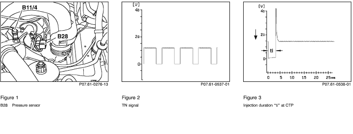
| 7.0 |
P 0 1 0 5 |
Pressure sensor (B28)
Sensor signal
(only  ) )
|
80
(24E) |
N3/10
|
79
(23E) |
Connect vacuum tester to pressure sensor (B28) using Y-fitting,
 23 (Figure 1). 23 (Figure 1).
Ignition: ON
Engine: at Idle
|
> 3.5 V
< 2 V and pressure climbs to > 500 mbar.
|
7.1 ,
Vacuum line,
Wiring,
B28 |
| 7.1 |
|
Pressure sensor (B28)
Voltage supply
|
80
(24E) |
N3/10
|
78
(22E)
|
Ignition: ON
|
4.7 - 5.3 V |
N3/10 |
| 8.0 |
|
Model 129, 140, 202
FP relay module (K27)
Model 210
Relay module (K40)
Activation
Current draw
K27 or K40 |
21
(29C)
8
(8A) |
|
2
(2A)
21
(29C)
|
 On Model 202,the activation of the fuel pump takes place via the On Model 202,the activation of the fuel pump takes place via the
passenger-side fuse and relay module box (K40/4).
Ignition: ON
The activation of the FP
occurs only once after
ignition "ON". For the
next activation, the
engine must have run
briefly.
Engine: Start
Ignition: ON
|
11 - 14 V for
approx.
1 sec.
11 - 14 V,
during starting
and while
engine runs
only.
0.1 - 0.3 A |
Wiring,
K27 or K40,
N3/10
|
| 9.0 |
P 0 1 1 5 |
ECT sensor (B11/4)
Voltage |
84
(28E) |
N3/10
|
85
(29E) |
Ignition: ON |
°C |
V |
9.1 ,
N3/10 |
| 20 |
3.4 |
| 30 |
2.9 |
| 40 |
2.4 |
| 50 |
1.9 |
| 60 |
1.5 |
| 70 |
1.2 |
| 80 |
0.9 |
| 90 |
0.7 |
| 100 |
0.5 |
±5 % |
| 9.1 |
|
Resistance (B11/4) |
84
(28E) |
N3/10
|
85
(29E) |
Ignition: OFF
Disconnect connector E
on engine control
module (N3/10). |
°C |
|
Wiring,
9.2 |
| 20 |
3090 |
| 30 |
2000 |
| 40 |
1330 |
| 50 |
900 |
| 60 |
630 |
| 70 |
440 |
| 80 |
320 |
| 90 |
230 |
| 100 |
170 |
±5 % |
| 9.2 |
|
ECT sensor (B11/4)
Resistance |
1 |
B11/4
|
2 |
Disconnect connector on ECT sensor (B11/4). |
Nominal value, see 9.1 |
B11/4
|
| 10.0 |
|
Engine control module (N3/10)
TN-signal output |
8
(8A)
8
(8A) |
|
30
(38C)
30
(38C)
|
Test with oscilloscope:
Engine: Start or
Engine: at Idle
Test with multimeter, only if test with oscilloscope is not possible. |
Signal, see
Figure 2
7.5 - 9.0 V |
Wiring,
N3/10 |
| 11.0 |
P 0 1 3 0
P 0 1 3 3 |
O2S 1
(before TWC) (G3/2)
O2S signal |
23
(31C) |
N3/10
|
24
(32C) |
If ECT > 80 ° C, run engine at idle for at least two minutes.
|
fluctuates from
- 0.2 V to + 1.0
V, by more than
0.3 V
|
Wiring,
12.0 ,
G3/2 |
| 12.0 |
P 0 1 3 5 |
O2S 1
(before TWC) (G3/2)
O2S heater activation
|
5
(5A) |
N3/10
|
2
(2A)
|
If ECT > 80 ° C, run engine at idle for at least two minutes. |
11 - 14 V |
Wiring,
G3/2
N3/10 |
| |
|
O2S 1 (G3/2)
Current draw |
3
(3A) |
N3/10
 |
5
(5A)
|
Ignition: ON |
0.6 - 3.4 A |
|
| 13.0 |
P 0 1 3 6
|
O2S 2
(after TWC) (G3/1)
O2S signal
(only ) |
39
(7D)
3
(3A)
3
(3A) |
|
40
(8D)
20
(28C)
66
(10E) |
If ECT > 80° C,
Engine: Start
Raise and hold engine
speed at 2000 - 3000
rpm for approx. 2
minutes.
Engine: at idle
Bridge sockets on socket box. |
Within one minute, the value range of 450 mV to 500 mV must be either exceed or be below value range given.
> 550 mV
AIR pump runs.
Voltage changes
to < 40 mV
within 60
seconds.
|
Wiring,
14.0 ,
G3/1,
N3/10 |
| 14.0 |
P 0 1 4 1
|
O2S 2
(after TWC) (G3/1)
O2S heater activation
(only ) |
9
(1B) |
N3/10
|
2
(2A) |
Engine: at Idle
If ECT > 80° C, run engine at idle for at least
2 minutes.
|
11 - 14 V
or voltage
fluctuates
between
1 - 14 V |
Wiring,
G3/1,
N3/10 |
| |
|
O2S 2 (G3/1)
Current draw |
3
(3A) |
N3/10
|
9
(1B)
|
Ignition: ON |
0.6 - 3.4 A |
|
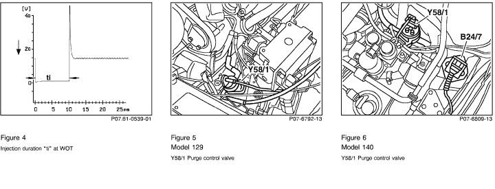
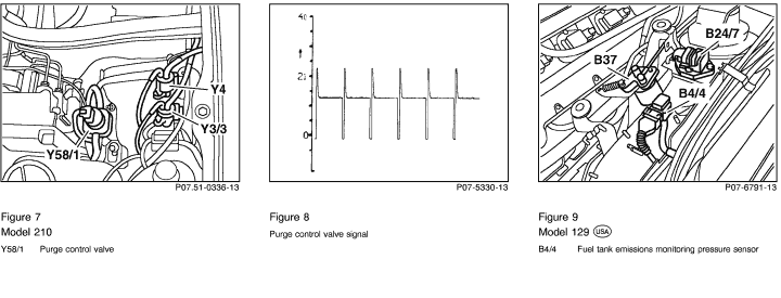
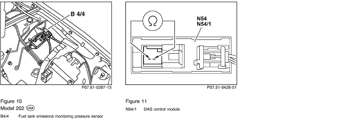
| 15.0 |
P 0 2 0 1 |
Injector (Y62y1)
Activation and injection time |
81
(25E) |
N3/10
 |
2
(2A) |
ECT approx. 20° C
at start:
ECT approx. 80° C
at idle:
accelerate briefly: |
Injection time:
approx. 8 ms
approx. 3 - 5 ms
approx. 14 ms
(signal see
Figures 3 and 4).
|
Wiring,
Y62y1,
N3/10,
ECT sensor (B11/4),
IAT sensor in hot film MAF sensor
(B2/5),
O2S 1 (G3/2). |
| |
|
Resistance (Y62y1) |
81
(25E) |
N3/10
|
2
(2A)
|
Ignition: OFF
|
14 - 17
|
|
| 16.0 |
P 0 2 0 2 |
Injector (Y62y2)
Activation and injection time |
57
(1E) |
N3/10
|
2
(2A) |
ECT approx. 20° C
at start:
ECT approx. 80° C
at idle:
accelerate briefly: |
Injection time:
approx. 8 ms
approx. 3 - 5 ms
approx. 14 ms
(signal see
Figures 3 and 4).
|
Wiring,
Y62y2,
N3/10,
ECT sensor (B11/4),
IAT sensor in hot film MAF sensor
(B2/5),
O2S 1 (G3/2). |
| |
|
Resistance (Y62y2) |
57
(1E) |
N3/10
|
2
(2A)
|
Ignition: OFF
|
14 - 17
|
|
| 17.0 |
P 0 2 0 3 |
Injector (Y62y3)
Activation and injection time |
69
(13E) |
N3/10
|
2
(2A) |
ECT approx. 20° C
at start:
ECT approx. 80° C
at idle:
accelerate briefly: |
Injection time:
approx. 8 ms
approx. 3 - 5 ms
approx. 14 ms
(signal see
Figures 3 and 4).
|
Wiring,
Y62y3,
N3/10,
ECT sensor (B11/4),
IAT sensor in hot film MAF sensor
(B2/5),
O2S 1 (G3/2).
|
| |
|
Resistance (Y62y3) |
69
(13E) |
N3/10
|
2
(2A)
|
Ignition: OFF
|
14 - 17
|
|
| 18.0 |
P 0 2 0 4 |
Injector (Y62y4)
Activation and injection time |
58
(2E) |
N3/10
|
2
(2A) |
ECT approx. 20° C
at start:
ECT approx. 80° C
at idle:
accelerate briefl: |
Injection time:
approx. 8 ms
approx. 3 - 5 ms
approx. 14 ms
(signal see
Figures 3 and 4).
|
Wiring,
Y62y4,
N3/10,
ECT sensor (B11/4),
IAT sensor in hot film MAF sensor
(B2/5),
O2S 1 (G3/2). |
| |
|
Resistance (Y62y4) |
58
(2E) |
N3/10
|
2
(2A)
|
Ignition: OFF
|
14 - 17
|
|
| 19.0 |
P 0 2 0 5 |
Injector (Y62y5)
Activation and injection time |
82
(26E) |
N3/10
|
2
(2A) |
ECT approx. 20° C
at start:
ECT approx. 80° C
at idle:
accelerate briefly: |
Injection time:
approx. 8 ms
approx. 3 - 5 ms
approx. 14 ms
(signal see
Figures 3 and 4).
|
Wiring,
Y62y5,
N3/10,
ECT sensor (B11/4),
IAT sensor in hot film MAF sensor
(B2/5),
O2S 1 (G3/2). |
| |
|
Resistance (Y62y5) |
82
(26E) |
N3/10
|
2
(2A)
|
Ignition: OFF
|
14 - 17
|
|
| 20.0 |
P 0 2 0 6 |
Injector (Y62y6)
Activation and injection time |
70
(14E) |
N3/10
|
2
(2A) |
ECT approx. 20° C
at start:
ECT approx. 80° C
at idle:
accelerate briefly: |
Injection time:
approx. 8 ms
approx. 3 - 5 ms
approx. 14 ms
(signal see
Figures 3 and 4).
|
Wiring,
Y62y6,
N3/10,
ECT sensor (B11/4),
IAT sensor in hot film MAF sensor
(B2/5),
O2S 1 (G3/2). |
| |
|
Resistance (Y62y6) |
70
(14E) |
N3/10
|
2
(2A)
|
Ignition: OFF
|
14 - 17
|
|
| 21.0 |
P 1 4 5 3 |
Model 129, 140:
AIR relay module (K17),
Model 202: Passenger-side
fuse and relay module
box (K40/4),
Model 210:
Relay module (K40)
Activation
|
20
(28C)
|
N3/10
|
2
(2A)
|
Disconnect ECT sensor
(B11/4) connector.
Simulate 2.5 k
resistance at sockets 1
and 2 with resistance
substitution unit.
Engine: at Idle
|
11 - 14 V
for approx. two minutes and AIR pump runs. |
Wiring,
AIR pump fuse,
K17, K40 or K40/4,
N3/10 |
| |
|
(K17), (K40), (K40/4)
Current draw |
3
(3A)
|
N3/10
|
20
(28C)
|
Ignition: ON |
0.1 - 0.3 A |
|
| 22.0 |
P 1 4 2 0 |
AIR pump switchover
valve (Y32)
Activation |
66
(10E) |
N3/10
|
2
(2A)
|
Disconnect ECT sensor
(B11/4) connector.
Simulate 2.5 k
resistance at sockets 1
and 2 with resistance
substitution unit.
Engine: at Idle |
11 - 14 V
for approx. two
minutes and
AIR pump runs. |
Fuse,
Wiring,
Y32,
N3/10 |
| |
|
Current draw (Y32) |
3
(3A) |
N3/10
|
66
(10E)
|
Ignition: ON |
0.4 - 0.6 A |
|
| 23.0 |
P 0 4 1 0 |
AIR system
(logic chain)
The O2S 1 signal before
TWC is being measured. |
23
(31C)
3
(3A)
3
(3A) |
|
24
(32C)
20
(28C)
66
(10E)
|
If ETC > 80oC run
engine at idle for at least
2 minutes.
Bridge sockets on socket
box |
The O2S
voltage
oscillates in the
area of -0.2 V
and +1.0 V
AIR pump runs.
Voltage
changes to <
100 mV within
20 seconds. |
Y32 binding,
AIR combi valve,
AIR pump no output.
|
| 24.0 |
P 0 8 0 2
P 1 2 2 5 |
Resonance intake manifold
switchover valve (Y22/6)
Activation |
68 (12E) |
N3/10
|
2
(2A) |
Engine: Start
Engine speed:
< approx. 3500 rpm
Engine speed:
> approx. 3500 rpm
|
< 1 V
11 - 14 V |
Wiring,
Y22/6,
N3/10 |
| |
|
Y22/6
Current draw |
3
(3A) |
N3/10
|
68
(12E)
|
Ignition: ON |
0.4 - 0.6 A |
|
| 25.0 |
P 1 5 2 5 |
Adjustable camshaft timing
solenoid (Y49)
Current draw |
1 |
Y49
|
2 |
Connect test cable
(102 589 04 63 00) to
solenoid.
Engine: at idle
ECT > 70oC
Increase engine speed to
approx. 2000 rpm.
|
1.0 - 1.5 A
|
25.1 ,
26.0 ,
N3/10 |
| 25.1 |
|
Resistance (Y49) |
60
(4E) |
N3/10
|
2
(2A)
|
Ignition: OFF |
7 - 12 |
Wiring,
Y49 |
| 26.0 |
P 1 5 1 9 |
Adjustable camshaft timing
solenoid (Y49)
Mechanical function |
60
(4E) |
N3/10

|
3
(3A)
|
Engine: at Idle
Bridge sockets on socket
box for a maximum of 10
seconds.
|
Engine runs
rough or stalls |
Check function of camshaft
adjuster (see SMS, Engine 104,
Job No. 05-2160). |
| 27.0 |
P 0 4 4 1
P 0 4 4 3
|
Purge control
valve (Y58/1)
Activation |
13
(21C) |
N3/10
|
2
(2A) |
Engine: at Idle
and at operating
temperature. |
After approx. 1
minute, purge
control valve
(Y58/1) must
noticeably cycle
(Fig. 5 to 7),
Signal see
(Figure 8).
|
Wiring,
Y58/1,
28.0 ,
N3/10 |
| |
|
Current draw (Y58/1) |
3
(3A) |
N3/10
|
13
(21C)
|
Ignition: ON |
0.3 - 0.5 A |
|
| 28.0 |
P 0 4 4 0
P 0 4 4 1
|
Purge control
valve (Y58/1)
Vacuum control |
|
|
|
Connect vacuum tester to purge control valve
(Y58/1) between purge line to charcoal canister
(Figure 5 to 7).
Engine at operating
temperature and at idle.
|
After approx.
1 minute,
> 50 mbar and
needle
oscillates,
Y58/1 must
cycle. |
Vacuum line,
Y58/1 |
| 29.0 |
P 0 4 4 0
P 0 4 4 2
P 0 4 4 6
P 0 4 5 5 |
Only
Model 140, 210 only,
Model 129 as of 09/97
Purge system
Leaks
Activated charcoal canister
shut-off valve (Y58/4)
Activate
|
3
(3A) |
N3/10
|
34
(2D)
|
Disconnect purge line (A) to charcoal canister on purge control valve
(Y58/1). Connect
vacuum tester to purge line (Figure 6 and 7).
Ignition: ON
Apply approx. 25 mbar of
vacuum.
|
After approx.
1 minute,
< 5 mbar
vacuum loss.
|
Fuel tank cap,
Purge line to charcoal canister,
Purge line from charcoal canister
to Y58/4,
Charcoal canister,
Y58/4
Charcoal canister,
Y58/4,
Purge control valve (Y58/1) |
| 30.0 |
P 0 4 4 6 |
Only
Model 140, 210 only,
Model 129 as of 09/97
Activated charcoal canister
shut-off valve (Y58/4)
Current draw
|
3
(3A) |
N3/10
|
34
(2D)
|
Ignition: ON |
0.5 - 0.9 A |
Fuse,
Wiring,
Y58/4 |
| 31.0 |
P 0 4 4 6
P 0 4 5 0
P 0 4 5 5 |
Only
Model 140, 210
Model 129 as of 09/97
Fuel tank pressure
sensor (B4/3)
Sender signal
Activated charcoal canister
shut-off valve (Y58/4)
activated
|
36 (4D)
3
(3A) |
|
37
(5D)
34
(2D) |
Disconnect purge line (A) to charcoal canister on purge control valve (Y58/1). Connect
vacuum tester to purge line (Figure 6 and 7).
Ignition: ON
Apply approx. 25 mbar of
vacuum.
|
> 2.9 V
< 2.3 V
|
31.1 ,
Wiring,
Vacuum line,
Charcoal canister plugged,
B4/3 |
| 31.1 |
|
Only
Fuel tank pressure
sensor (B4/3)
Voltage supply |
36
(4D) |
N3/10
|
38
(6D)
|
Ignition: ON |
4.7 - 5.3 V |
N3/10 |
| 32.0 |
P 0 4 5 0
|
Only
Model 129, 202 up to 08/97
Purge monitoring pressure
sensor (B4/4)
Sender signal |
36
(4D) |
N3/10
|
37
(5D)
|
Disconnect purge line (A) to charcoal canister on purge monitoring pressure sensor (B4/4).
Connect vacuum tester to purge monitoring pressure sensor (Figure 9 and 10).
Ignition: ON
Apply approx. 300 mbar
of vacuum.
|
> 3.5 V
< 3 V
|
Wiring,
32.1 ,
B4/4 |
| 32.1 |
|
Purge monitoring pressure
sensor (B4/4)
Voltage supply |
36
(4D) |
N3/10
|
38
(6D)
|
Ignition: ON |
4.7 - 5.3 V |
N3/10 |
| 33.0 |
P 0 6 0 0
P 0 8 1 1
P 1 5 7 0
P 1 6 0 3
P 1 7 4 7
|
CAN data bus
|
43
(11D) |
N3/10
|
44
(12D) |
Ignition: OFF
|
55 - 65 |
33.1 - 33.2,
Data line. |
| 33.1 |
|
CAN element in DAS
control module (N54/1)
Resistance |
43
(11D) |
N3/10
|
44
(12D) |
Ignition: OFF
Disconnect connector D
from engine control
module N3/10,
(Figure 11).
|
115 - 125 |
Wiring,
N54 or N54/1 |
| 33.2 |
|
CAN element in engine
control module (N3/10)
Resistance |
43
(11D) |
N3/10
|
44
(12D)
|
Ignition: OFF
Disconnect connector D
from test cable.
|
115 - 125 |
N3/10 |
| 34.0 |
P 1 1 6 3 |
Oil level switch (S43) |
73
(17E) |
N3/10
|
2
(2A) |
Ignition: ON
Oil level okay:
Oil level low:
|
11 - 14 V
< 1 V |
Wiring,
S43 |
| 35.0 |
|
Diagnosis line
Activation |
3
(3A) |
N3/10
|
31
(39C)
|
Ignition: ON
|
11 - 14 V |
Wiring,
N3/10 |


 Printable version