
Diagnostic Manual, Chassis and Drivetrain,
Volume 3
Electrical Test Program - ASR V / ETS Component Locations
Preparation for Test
1. Review section 0 entirely before starting Electrical Test Program.
2. Additionally review:  21, 22, 23(connector connections). 21, 22, 23(connector connections).
3. Review the following ETM diagrams:
PE00.19-P-1100B
PE42.00-P-1100B
PE00.19-P-1100D
PE42.00-P-1100D
PE00.19-P-1100A
PE42.00-P-1100A
4. Review control module CAN data, starting with 22/6
5. Ignition: OFF
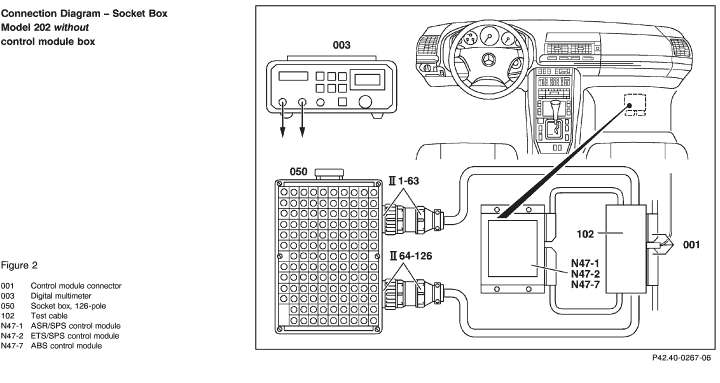
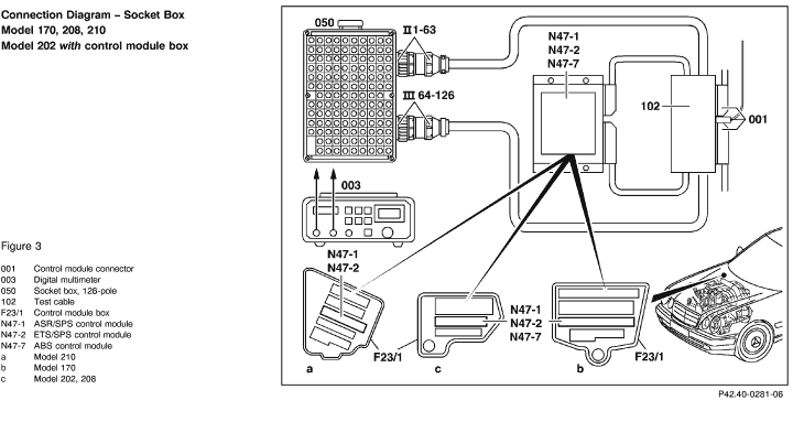
6. Disconnect traction control module (N47).
7. Connect socket box with test cable as per connection diagram
(Figures 1-3).
8. Perform test steps.
Electrical Wiring Diagrams:
(location of grounds and connectors).
Electrical Troubleshooting Manual, Models 129, 140, 170, 202, 208, 210

When exchanging an ETS/SPS control module, the replacement module must have the code data entered via the HHT. Follow instructions as given by HHT display. In order to code the control module, select "?" on HHT key pad.
The electrical test includes ETS, ASR and SPS. In order to avoid listing all traction control modules (ABS [N47-7], ETS [N47-2], ASR [N47-1]) and all hydraulic units (ASR/ETS/ESP [A7/3]) used in the traction control systems, the general designation N47 (traction control module) will be used for all traction control modules, and A7/3 (ASR/ETS/ESP hydraulic unit) for all traction control hydraulic units, regardless of what is actually installed in vehicle.
|
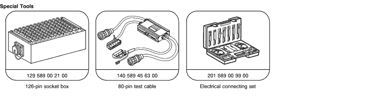 |
Test Equipment; See MBUSA Standard Service Equipment Program
| Description |
Brand, model, etc. |
| Digital multimeter |
Fluke models 23, 77 III, 83, 85, 87 |
|


 Printable version
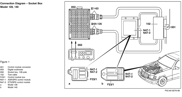
 Brake lining wear indicator lamp (A1e6)