Preliminary work:
Diagnosis - Malfunction Memory  11 11 |
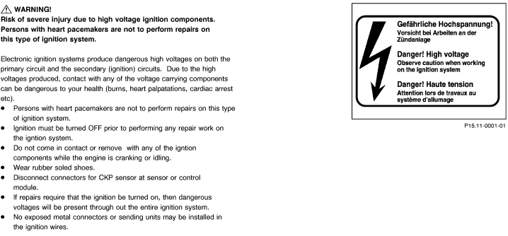
 WARNING! WARNING!
Risk of severe injury when touching ignition parts which produce high voltages. Do not touch ignition components.
Persons with heart pacemakers are not to perform repairs on this type of ignition system.
1. Review WARNING! on pages 11/1 and 11/2,
2. Review 11, 21, 22 , 23, 24, 31, 33 ,
3. Review section 0,
4. Connect HHTand readout DTC memory, see 11 ,
5. Ignition: OFF
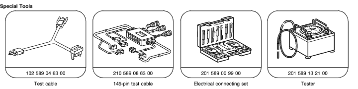
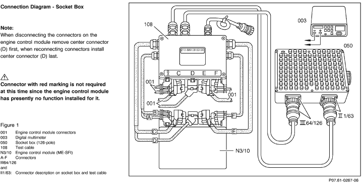
6. Connect test cable with socket box as per "Connection Diagram - Socket Box", see 22 /5.
Electrical wiring diagrams:
Electrical Troubleshooting Manual, Model 129,
Electrical Troubleshooting Manual, Model 140,
Electrical Troubleshooting Manual, Model 202,
Electrical Troubleshooting Manual, Model 210.

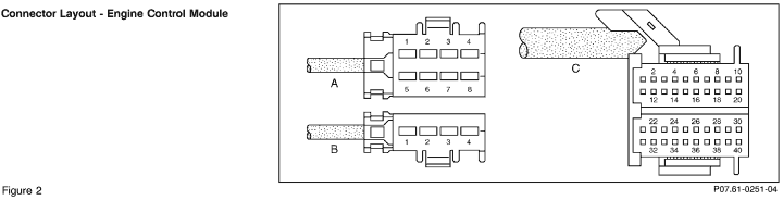
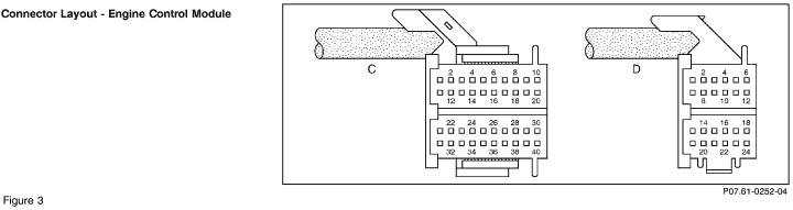
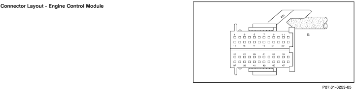
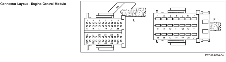
Connector with red marking is not required at this time since the engine control module has presently no function installed for it.
When disconnecting the connectors on the engine control module remove center connector (D) first, when reconnecting connectors install center connector (D) last.
Note regarding "Test Connection" column:
The numbers indicated in parentheses, for example,  1.0 (2A) signify: 1.0 (2A) signify:
2 = Socket 2 on wiring diagram.
A = Connector A on wiring diagram
Note:
The test program is divided into four sections:
23 SFI Test
24 Ignition System Test
25 EA System Test
26 CC System Test |
 |
 |
Test equipment; See MBUSA Standard Service Equipment Program
| Description |
Brand, model, etc. |
| Digital multimeter |
Fluke models 23, 77 III, 83, 85, 87 |
| Engine analyzer |
Bear DACE
Hermann Electronic |
 |
To Avoid Damage to the Ignition System
 To avoid damage to the engine control module, connect/disconnect the control module connectors only with the ignition: OFF To avoid damage to the engine control module, connect/disconnect the control module connectors only with the ignition: OFF
Circuit 1 of the ignition coil may not be shorted to ground, e.g. theft deterence.
Only original equipment should be installed in the ignition system.
Do not operate the ignition system at cranking speed unless the entire igntion harness is connected.
Do not perform any tests (grounding of ignition cable 4 disconnecting a spark plug connector or pulling cable 4 out of the ignition coil) at cranking or idle speed.
The high output side of the ignition system must carry at least 2 k  of load (spark plug connector). of load (spark plug connector).
If assisting a disabled vehicle and it becomes necessary to perform an igntion spark test, perform this test only on one ignition/sark plug. Ensure a good ground connection to the spark plug.
ME - SFI: the ignition system is to be turned OFF, when cranking engine to perform compression tests, additionally, it is necessary to disconnect connector 2 from the control module.
CFI/LH-SFI: disconnect connector(s) on DI control module for CKP sensor (L5).
CFI/LH-SFI: The DI control module, which is mounted on the wheel arch, is coated with a heat absorbing paste to enhance the transfer of heat, therefore do not remove the foil strip, since this has no negative effect on the heat transfer.
Engine 120 has two separate ignition and fuel injection system
Using Test Equipment
Ensure that the engine and ignition are OFF when connecting/ disconnecting test equipment to a coil.
Connect the secondary voltage measuring equipment on the corresponding secondary ignition lead only when engine is stopped and ignition is OFF.
If the circuit breaker is activated (power balance test), and the engine stalls, then the test procedure with this tester cannot be performed.
Do not connect a test lamp to circuit 1 or 15 of the ignition coil. |
 |
 |
 |
 |
 |
|


 Printable version